Rotary Encoder D-Pad
thingiverse
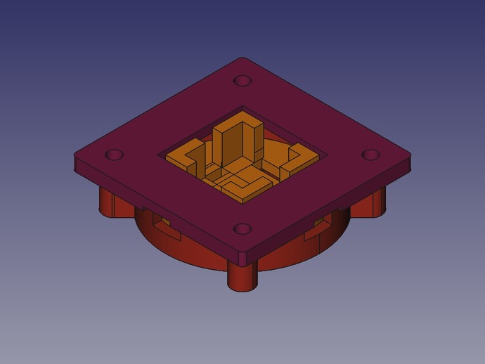
An assembly that takes a standard rotary encoder and adds the ability to sense when the encoder is pushed in 4 directions. It also supports a center button if it is built in to the rotary encoder without activating any of the other directions. It does this by having a disc that holds the rotary encoder balance on a cone in the bottom holder. This will allow it to rotate along the X and Y axis enough to push buttons on the top of the assembly. This is the first part I designed to be printed and is for a small raspberry pi and xbmc based kitchen radio/viewer so most functions could be performed with one knob. Other Parts: Rotary Encoder: PEC11-4220F-S0024, Newark #02J2850 I'm not sure what the part number is for the push buttons used, but they have a base of 6.5mm squared and the full height with the button not pressed is 5.0mm. The lower limit of the switch makes the height 4.75mm Instructions Print all three parts. Depending on your printer, you may need to clean up the parts to make sure there are no stringers and the surfaces are smooth. When I printed the center rotary encoder holder, I could not get the bottom indent to print correctly, so I corrected it with a dremel. Assemble the parts temprarily to make sure the center holder can move up, down, left, and right, but not rotate along the Z axis. Attach four small push buttons to the bottom of the lid. I used hot glue in this case, which seems to work well so far. Make sure leads are point out. Solder wires on the rotary encoder and feed the wires through the holes in the holder. Glue in place. Feed the encoder's wires through the holes in the bottom container and make sure the holder can still move. It may help putting a layer of masking tape between the bottom container and the holder. This will make the holder stay center and provide a better feel in the completed unit. Attach the top to the bottom container using 4x M3x20 screws and nuts. The holes may need to be drilled a bit wider if the print was not accurate. Finally, solder wires to the four push buttons and connect them to your board as you would any other switch. You should now feel satisfying clicks when moving the encoder up down left and right. If it is too tight, you can place washers between the bottom and top components until you get all four buttons in the open state when not pushing the encoder. Enjoy and happy hacking! -Leo
With this file you will be able to print Rotary Encoder D-Pad with your 3D printer. Click on the button and save the file on your computer to work, edit or customize your design. You can also find more 3D designs for printers on Rotary Encoder D-Pad.