Rotating display table - USB powered, with light
thingiverse
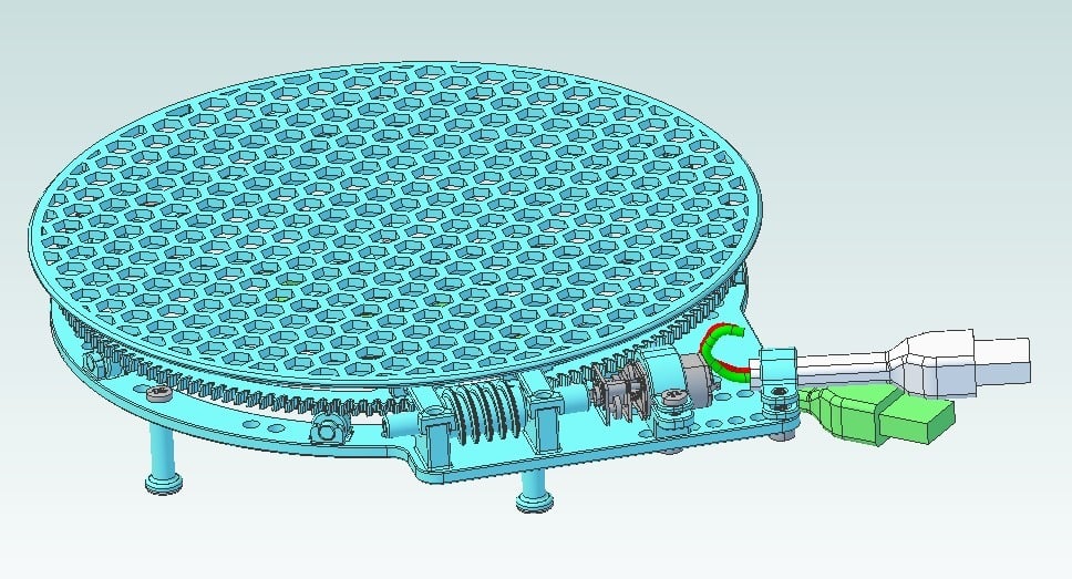
160 mm diameter rotating display table; to showcase products or items. Motor and light powered by USB. Please read assembly instructions before building -- left as "work in progress" because of the mechanical assembly process (but if you've built a 3D printer, this shouldn't be too challenging). Power from anything other than a charger or powerbank at your own risk. [ UPDATE 19/09/17: Added zipped IGES CAD files and turntable V2 STL ] Assembly: 1) Print the large base (large flat side down) 2) Print the large turntable/worm-gear (a large flat side down) 3) Check the fit of the turntable to the base. The base's central post may have a nub to be trimmed at one quadrant (if your retract on layer change isn't sufficient). The turntable should spin smoothly. Don't install a screw yet, remove the turntable. 4) Print the motor spacer; either GM 20 or 130 version. The GM20 is for a gear-head motor that will provide a more suitable RPM. The worm stage gives ~ 150:1 reduction ... so a 300 RPM gear-head motor will provide about 2 RPM at the table. 6V, 300 RPM: http://www.ebay.com/itm/DC3V-6V-12V-N20-Micro-Speed-Reduction-Gear-DC-Motor-with-Metal-Gearbox-Wheel-New-/172018005599?var=&hash=item280d12765f:m:mCbH1jM0wwRJc-lzsdrwl6w 5) Mount the motor to the base using M3 x 5 screws (3X). The screws are essentially self-tapping. 6) Hack a USB cable to power the motor (red and black wires, model rendering incorrectly shows green). Before soldering the wires, check that the motor spins clockwise (looking into the shaft). Example of USB cable hack: http://www.instructables.com/id/Really-REALLY-Easy-USB-Motor/ This USB light is inexpensive and we'll use one later; you could buy two and hack one for the cable. http://www.ebay.com/itm/Flexible-USB-LED-Light-Lamp-for-Computer-Keyboard-Reading-PC-Laptop-Notebook-LT-/182190927305?hash=item2a6b6cedc9:g:UcIAAOSwhOVXdhft 7) Print the worm (STL is mislabeled as wormgear). There's a monolithic STL and two half files. The halves worked better for me (no supports, no bed adhesion, slow speed). Print the halves at the same time (rotate one so both flats are down). The tippy-top is thin thin, so if you have a part cooler, you may get better parts than mine. Super glue the halves together ... you can (probably should) use the base as a gluing fixture to ensure lateral alignment. It is critical that the halves are well aligned. 8) Mount the worm to the motor (super/CA glue if needed). You may need to uninstall the motor to mount the worm. 9) Print five legs and install them with M3 x 5 screws. Print standing up (a flat side down). The machine screws should be effectively self-tapping. 10) Print the display table (large flat down) and rest it atop the turntable/wormgear. 11) Install the USB light with a M3 X 8 screw. Install the bracket for the motor's USB cable using one M3 X8 screw as well. https://youtu.be/ntqrUvoIp3o https://youtu.be/QXLqqfMkZFA
With this file you will be able to print Rotating display table - USB powered, with light with your 3D printer. Click on the button and save the file on your computer to work, edit or customize your design. You can also find more 3D designs for printers on Rotating display table - USB powered, with light.