RPi-Power-Bar
thingiverse
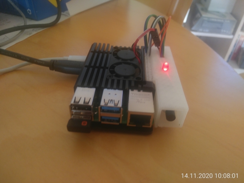
Raspberry Pi Power Bar ================== I've now encountered several situations, where having better control over the Raspberry Pi power would have been really useful. One scenario is the "headless" use, where there is no keyboard and no monitor connected to the Rpi, another is the use in a desktop scenario. I currently have two Raspberry Pi 4 - one running Octoprint so I can remote control my Prusa Printer (headless use), the other running Ubuntu 20.10 on the desktop. Both of them require rather massive cooling and it is annoying to not be able to start them up / shut them down right where they are without having to resort to (remote) logins. When you research on the Internet, you will find that there are quite simple solutions to the three issues "Power Switch", "Power Indicator" and "Temperature controlled active cooling" - but alas, it does not look like they have ever been combined and there also is no simple solution to attach the required electronic parts to the Pi. This project proposes a straight forward and rather simple solution to the problem: A 3d printed "Power Bar" to take the on/off switch, the power indicator led and some circuitry to PWM control a fan attached to the GPIO pins of the Pi. Printing instructions -------------------------- Printing this project is not quite as easy as it seems to be: The walls of the 40 pin Dupont connector are quite thin, and I had to experiment with the settings in the Slic3r PE program (recognize thin walls, add additional contours if needed) to get this to print properly. You will definitely want to preview the slicer output (check for missing walls, especially in the connector area) before you print it! Electronics --------------- Essentially there are three separate circuits that need to be built inside the power bar and because each of them only consists of a maximum of three parts I did not use a PCB, but connected (soldered) them "on the fly" as needed, wrapped in shrink tubing for protection and insulation. I also bought a crimp tool and some connectors for this project that had been on my wish list for some time so I could properly connect the electronics to the pins on the Raspi. The circuitry shown in the photos does not quite match the circuit diagram in that I only used one connection to ground. You can just implement part of the functionality by omitting the circuits you do not want or need - they really are three completely independent functions. Software ------------ The following settings must be configured in the config.txt file of the Raspi: * For the on/off switch: > dtooverlay=gpio_shutdown,gpio_pin=4,active_low=1,gpio_pull=up * For the power control led: > enable_uart=1 If you want the temperature contolled fan to operate, you will need to copy the attached python program fan_ctrl.py to /root, the fanctrl.service file goes in /etc/systemd/system. Thr RPi.GPIO python library is installed by default in the Rasbian image, but needs to be installed manually on ubuntu 20.10 (apt install python3-rpi.gpio). Don't forget to reload systemd (systemctl daemon-reload) and to enable the service (systemctl enable fanctrl), otherwise it will not be started on boot. Updates ----------- 22.11.2020: Re-upload the main STL file. Replaced Dupont connector initially based on https://www.thingiverse.com/thing:3392377 with my own design and improved printability by shrinking the connector access window and slightly increasing the connector access shield. This should now print without holes on either side of the connector. 27.11.2020: Update circuit diagram to highlight the three separate circuits. Add photo of another print. Also add two more files that implement a shutdown hook for installations that have no built-in handler for the power signal. The install procedure for this service is the same as for the fanctrl service. Note that this is usually only needed for headless installations! References --------------- * My 3d design: https://www.tinkercad.com/things/b9n5rtG8rFP * RPi GPIO pinout: https://pinout.xyz/# * Power Button: https://howchoo.com/g/mwnlytk3zmm/how-to-add-a-power-button-to-your-raspberry-pi * Power LED: https://howchoo.com/g/ytzjyzy4m2e/build-a-simple-raspberry-pi-led-power-status-indicator * PWM controlled fan: https://www.instructables.com/PWM-Regulated-Fan-Based-on-CPU-Temperature-for-Ras/ * Circuit Diagram Editor: https://www.circuit-diagram.org/editor/ * Crimp Tool: https://www.amazon.de/dp/B078K9DT69 * Diodes: 1N4148 * Transistor: BC377
With this file you will be able to print RPi-Power-Bar with your 3D printer. Click on the button and save the file on your computer to work, edit or customize your design. You can also find more 3D designs for printers on RPi-Power-Bar.