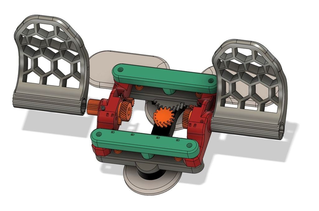
Rudder Pedals for Flight Sims - Heavy Duty
thingiverse
Last updated 16-02-2023 It's an upgrade for an awesome design: https://www.thingiverse.com/thing:4655002 My problems with the original, and changes made: - The holes for brass inserts ware 5.2mm. Changed to 4mm for M3 brass inserts. - All Screw holes for M4 were exactly 4mm even in places where the screw should be loose. Changed to 4.1mm - 4.2mm. - Bearings had almost no function in original project - when you place 608 bearings on a flat surface, both the outside and the inside of a bearing touches the same surface and the bearing stops functioning almost completely. Redesigned for smooth and frictionless operation. - All bearing sockets redesigned to have 3mm depth in both top and bottom parts, and with proper bearing operation under load in mind. - The printed parts were rubbing each other. Now bearings allow for 0.5-1mm space separating the parts. - The nuts used were all without a nylock which would help a bit. - C_pot_gear had no clearance from base, this resulted in some friction. Changed to add 1mm clearance. - Tension arm bearing height raised by 1mm to make it inline with b_bottom_bar. - All the problems above made the screws to tighten and loosen every time you move the pedals forward and back. Fixed :) - Not adjustable pedal angle. I redesigned the pedal gear and I've added blocking screw, allowing for easy pedal angle adjustment and disassembly (PVC version)! - Difficulty in mounting arduino - added holes for brass inserts. - Difficulty in routing cables - added zip tie holes. - 2 kinds of springs - now only 45x1mm spring is needed (3 springs) - Stability, this one was probably the biggest problem for me. The pedals would flex a lot under legs weight, and they would wobble to the sides too much for my liking. The top bars eliminated the first problem completely and made the construction almost bullet proof. The big central bearings fixed the second problem. Sorry for adding less common bearings to the design but trust me it's worth it. - The PVC tubes were binding under load, added a variation that uses M8 threaded rods and 4 additional 608 bearings instead of the pvc tubes. That's what I'm recommending you to use. Additional hardware needed: - Arduino Pro Micro (Leonardo) ATmega32U4 - PCB and 2.54mm pins to mount arduino, 3x ceramic capacitors (1pf-100pf) - micro usb cable Platforms: 4x M3x8 screws and nuts 6x M3x8 Base: 9x M3 brass inserts 2x M4 Nuts 3x M3x5 screw for the spring and arduino 2x 6004 bearing 42mm x 20mm x 12mm Tension arm: 1x M3 brass insert 2x M4 nuts 1x M3x5 screw for the spring 1x M4x10 screw 1x M4x20 screw and washer for the bearing 1x 608 bearing Bottom arms: 4x M4 nuts 4x M4x10 screws for blockers 2x M4x30 central screws 2x F4-9 M bearings 4x9x4mm (https://pl.aliexpress.com/item/4000211379068.html) Pedal brackets: 6x M4x10 screws for the springs and as gear limiters 8x 608 bearings Top Arms: 4x M4x50 as corner screws connecting top arms, the pedal brackets and bottom arms. Pedals 2x M4x10 screws for the springs 3x springs: 45mm length x 1mm wire thickness. PVC version: 2x 3/4' PVC tube (EU standard), 170mm length, with 5mm cutouts on both sides. Check pvc_pedal_gear design for details. The outside of the tube should be close to 27mm, and inside close to 22.5mm. PVC locker: 2x M4x30 screw, nut and washer M8 threaded rod version: 2x M8 165mm threaded rod or a M8x150 screw - make sure it has thread on the whole length. 4x 608 bearings 12x M8 nuts Strong thread glue like loctite 270 Printing check list: 2x tension_arm_bearing_spacer_print_two.obj 2x Pedal_pot_gear.stl 8x bearing_spacer.obj for 608 bearings 4x stopper 1x C_B_Platform.stl, L_B_Platform.stl, R_B_Platform.stl, F_L_Platform.stl 1x F_B_Grip.stl, L_B_Grip.stl, F_F_Grip.stl, R_B_Grip.stl, C_B_Grip.stl 1x base.obj, F_Bottom_Bar.obj, B_Bottom_Bar.obj, F_Top_Bar.obj, B_Top_Bar.obj 1x C_Pot_Gear.obj 1x Tightening_Screw.stl for PVC pipe version: 2x PVC_pedal_gear_holder_ext.obj 2x PVC_pedal_gear_holder_int.obj 2x PVC_Pedal_gear.obj 1x PVC_Pedal_bracket_L and PVC_Pedal_bracket_R 1x PVC_Pedal_L.obj and PVC_Pedal_L.obj for M8 Threaded Rod version: 2x M8_Pedal_gear.obj 2x M8_Pedal_angle_gear.obj 1x M8_Pedal_bracket_L and M8_Pedal_bracket_R 1x M8_Pedal_L.obj, M8_Pedal_R.obj One more thing. If your using the original code for arduino from: https://create.arduino.cc/editor/vince_prints/45cb8720-345c-4a7b-a015-896cedd0fbbd/preview delete lines: leftPedal = map(leftPedal,0,1023,0,255); rightPedal = map(rightPedal,0,1023,0,255); rudderAxis_ = map(rudderAxis_,0,1023,0,255); the author is dividing resolution of the readout by x4, it's unneeded as both the arduino ADC and joystick library are using 10bit resolution by default (0-1023 range) and windows uses 16bit resolution. Consider adding a ceramic capacitor between every signal line and ground to the pcb board. The closer the capacitor will be to the arduino the better. It will stabilise the potentiometer readouts. Pick a value between 1pf and 100pf, the more capacitance the stronger smoothing will be - and more delay will be introduced.
With this file you will be able to print Rudder Pedals for Flight Sims - Heavy Duty with your 3D printer. Click on the button and save the file on your computer to work, edit or customize your design. You can also find more 3D designs for printers on Rudder Pedals for Flight Sims - Heavy Duty.