Runcam Split intervalometer
thingiverse
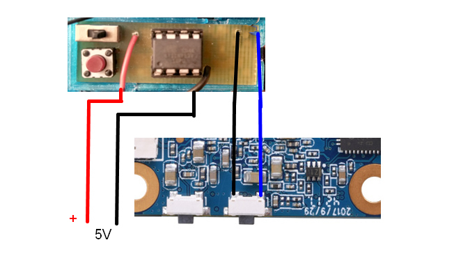
Unfortunately the Runcam Split has no built-in feature to auto-shot in intervals when it's set to photo mode. So I designed this little board to do the job. When it's switched on, the interval is set to 1 second. Each time you press the small button, another second is added. So if you want a 5-second interval, you just press it five times, if you want 10-second intervals, press it ten times and so on. The LED on the bottom side will flash for the first 10 cycles so you can control your settings. The Runcam PCB is connected through an optocoupler, making it completely isolated from the timer PCB. Use thin wire and a small tip to carefully solder the wires to the tiny switch on the Runcam board. For wiring reference, see the pictures. They show just the wiring for the Runcam Split V2. For the V1, I can't guarantee similarity but it should be close. PARTLIST: 1x ATtiny13 1x 8-pin IC socket 2x SMD resistor 220 Ohm (1206) 1x SMD resistor 10 kOhm (1206) 1x SMD LED (1206) 1x optocoupler PS2501 (or KB357N2T, etc.) 1x tactile switch (OMRON or similar) 1x miniature slide switch Thanks to David Watts who shared this schematic and the code. To flash the code into the ATtiny13, you can use an Arduino Uno: https://create.arduino.cc/projecthub/taunoerik/programming-attiny13-with-arduino-uno-07beba The *.brd and *.sch files are for EAGLE (if you want to redesign the PCB). The PCB layout and Arduino code are within the ZIP file. I also added two STL files for a small housing. One with holes for screws, one without (for clipping)
With this file you will be able to print Runcam Split intervalometer with your 3D printer. Click on the button and save the file on your computer to work, edit or customize your design. You can also find more 3D designs for printers on Runcam Split intervalometer.