Runtime counter v. 2.1
thingiverse
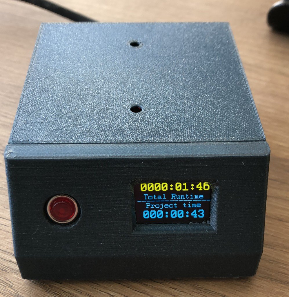
Runtime counter v 2.1 This is a remake/update of the Runtime counter v 2.0 witch was made to count one time. The purpose of this project is to make a Runtime counter for your machines like a 3D-printer or Laser module on a CNC machine or whatever kind of working time you wish to count and save. But now it has a added feature to keep track of the time you spend on a particular project, afterwards you can reset this time to zero for another project. The power comes from: AC to DC convertor 110-240V AC to 6V 600 mAmp DC. 6-24V pin of one of the machines, this is converted by the mini 360 stepdown buck converter to 5.5V for the microcontroller Pro Mini 5V (connect at RAW pin). The Pro Mini seems not like more voltage (I fried some on 9 and 12V). The Nano can handle up to 12V. 5V direct to micro controller on VIN, RAW, or VCC pin. All other components are powered by the VCC or +5V pin of the Pro Mini and Nano. Changelog: Version 2.0 (October 2022) The Fram FM25L16B-GTR is replaced by an Adafruit breakout board with a MB85RC256V chip, this requires a partial new Arduino code. The components are now placed on a print. The microcontroller and Fram are placed in female headers on the print to make it easier to change those components for update(code) or other use in the future. The Oled display is via I2C protocol and a 4 pin JST-XH wire connected to be flexible for placement. Version 2.1 (march 2023) The code is updated for 2 timers. The display is replaced by an 0,96” dual color Oled. An extra pushbutton for “reset” project timer. New housing for electronic components. Libraries used for the Arduino are: Fram library used: FRAM_I2C ( https://github.com/RobTillaart/FRAM_I2C ) Oled library used: U8g2_Arduino ( https://github.com/olikraus/U8g2_Arduino ) Appendixes supplied: Arduino source code : Dual Runtimer v.2.1.ino Print layout in PDF : Dimensions of print: 34 x 64mm for Pro Mini (30 x 70mm for Nano) Create the PCB in PDF : How to explanation to make your own PCB Electronic scheme in PDF: Explanation wiring options Hardware: Microcontroller: Arduino NANO, Arduino Pro Mini 5V FT232RL FT232 Ftdi Usb ( https://nl.aliexpress.com/item/32460118879.html ) Interface needed to send the program code from the computer (usb) to the Pro Mini (serial) 0.96 " Oled Display (128x64)( https://nl.aliexpress.com/item/32844104782.html ) Fram Breakout Board ( https://nl.aliexpress.com/item/1005003077716200.html ) Power other than 6V, Mini 360 DC-DC Buck Converter ( https://aliexpress.com/item/1005001505367325.html ) AC-DC convertor 70- 270V AC to 6V DC 600 mAmp max ( https://nl.aliexpress.com/item/1005005074746000.html ) Female and Male headers, 2 pole Screw terminal, 2x 10K Ohm resistor, Print mount tact switch, JST-XH print mounted 4 pin terminal (to display) or male headers, 2 Female 4 pin JS-XH Female plugs (for display) alternative you can use female-female DuPont wires. 4x M3 – 6mm screws
With this file you will be able to print Runtime counter v. 2.1 with your 3D printer. Click on the button and save the file on your computer to work, edit or customize your design. You can also find more 3D designs for printers on Runtime counter v. 2.1.