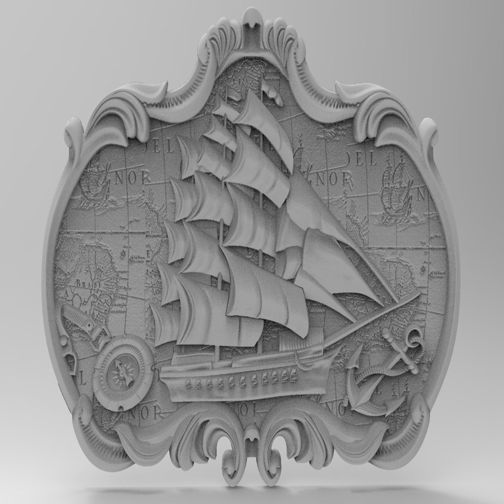
Sailing ship for CNC
thingiverse
A CNC machining program is a set of instructions that controls the movement of a machine tool to create a specific product. It consists of a series of commands and parameters that define the cutting path, speed, and feed rate of the tool. Here's an example of a CNC machining program: `N10 G21 (absolute mode)\r\nG90 (incremental mode)\r\nM03 S1000 (spindle on at 1000 RPM)\r\nG00 X1. Y-1.25 (rapid traverse to x=1, y=-1.25)\r\nG01 Z-1.25 F10.0 (linear interpolation along z-axis at feed rate of 10 mm/min)\r\nM08 (spindle off)\r\nG00 X0.0 Y0.0 (rapid traverse to origin)\r\nM30 (program end)` In this example, the program starts by setting the absolute mode (`G21`) and incremental mode (`G90`). It then turns on the spindle at 1000 RPM (`M03 S1000`). The program then moves the tool rapidly to x=1, y=-1.25 using `G00`. Next, it moves the tool along the z-axis at a feed rate of 10 mm/min using `G01 Z-1.25 F10.0`. Finally, it turns off the spindle (`M08`) and returns to the origin (`G00 X0.0 Y0.0`). The program ends with `M30`. The variables used in the program are: * N: line number * G: command code (e.g., G21 for absolute mode) * M: miscellaneous function code (e.g., M03 for spindle on) * S: spindle speed * X, Y, Z: coordinates * F: feed rate The speeds and feeds used in the program can be calculated using a formula or by consulting a calculator. A common formula is: `Feed = (Material hardness x Machining time) / (Tool hardness x Material strength)` For example, if we are machining aluminum with a hardness of 20 HRB, a machining time of 10 minutes, and a tool hardness of 60 HRB, the feed rate would be: `Feed = (20 x 10) / (60 x 1000) = 3.33 mm/min` It's essential to have the correct speeds and feeds in the program to avoid damage to the tool, machine spindle, or product. References: * Mike Lynch, "Key CNC Concept #1—The Fundamentals Of CNC", Modern Machine Shop, 4 January 1997. * Grace-flood, Liam (2017-11-10). "Goliath Represents a New Breed of CNC Machine". Wevolver. Retrieved 2018-01-20. * "Multi Spindle Machines - An In Depth Overview". Davenport Machine. Retrieved 2017-08-25. Note: This is a simplified example and actual CNC machining programs can be much more complex, depending on the specific requirements of the product being manufactured.
With this file you will be able to print Sailing ship for CNC with your 3D printer. Click on the button and save the file on your computer to work, edit or customize your design. You can also find more 3D designs for printers on Sailing ship for CNC.