Second Fan Mount for CR-10S Pro and SKR v1.1 Pro / 1.3 / 1.4 Turbo - Dual Noctua NF-A4x20 FLX Fans wired for 24V
thingiverse
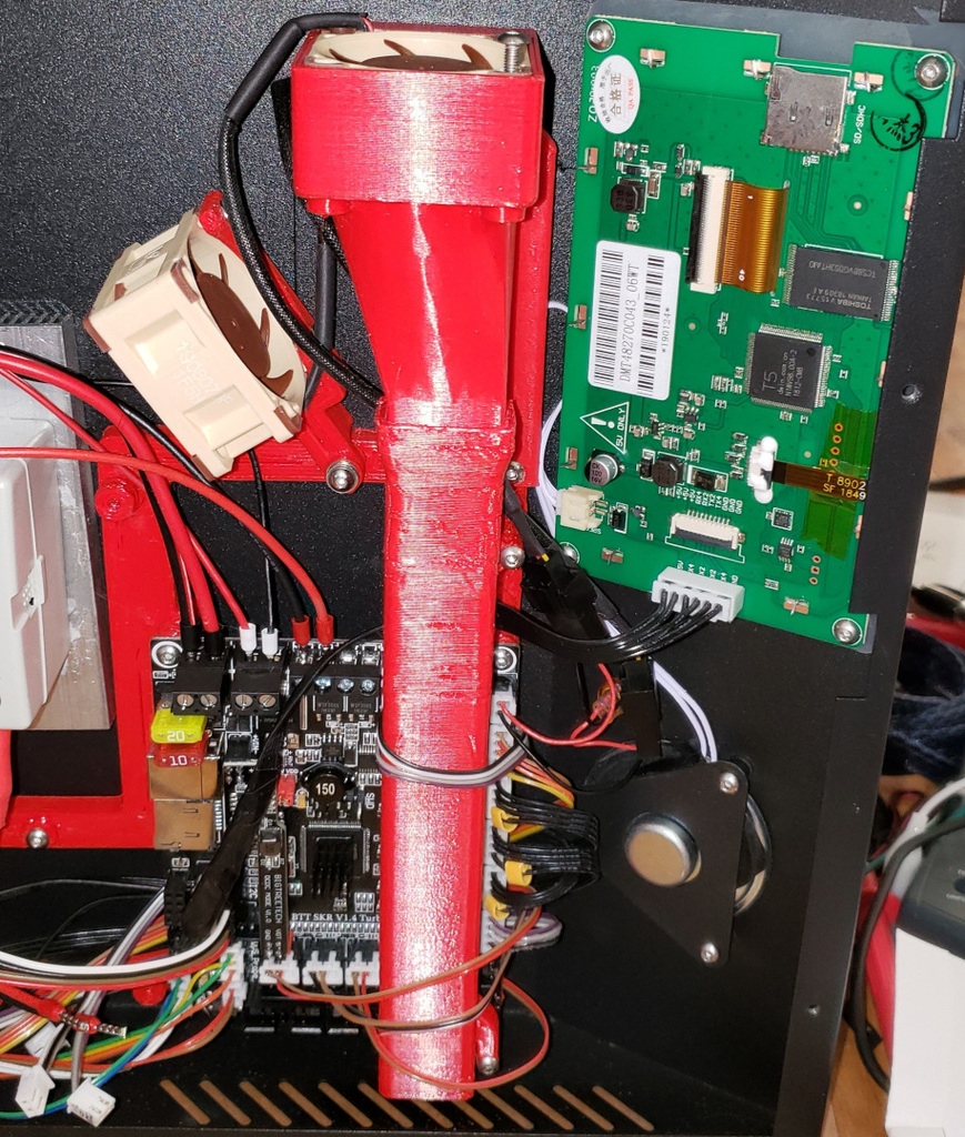
This thing is a small bracket meant to add a second fan to a SKR board / CR10-S Pro combination. This secondary fan bracket works with SkullKill's SKR Mount. First, you will need SkullKill's SKR Mount itself, the fan duct (Note: I have a customized version of the large fan duct that fits the heatsinks on the SKR V1.4 boards even better here: https://www.thingiverse.com/thing:4672639) Yes, his mount does work for the V1.4 and V1.4 Turbo SKR Boards: <a href="https://www.thingiverse.com/thing:3980507">https://www.thingiverse.com/thing:3980507</a> I have tested this secondary fan mount bracket with the SKR V1.4 Turbo. I have not tested it with the V1.1 Pro or V1.3 boards, but think it could/should work for those as well. Some hand fitting may be required to provide enough clearance. Second, you will need two each: Noctua NF-A4x20 FLX Fans wired in series. Do not attempt this if you don't understand series wiring, or don't understand how two 12V fans can be wired together so that they can be powered by 24V. You can see my picture above for help, but beyond that you are responsible for your own wiring and understanding how this works. These fans come with a female connector that has a wire pigtail coming off of it. They also come with press to connect wire connectors. You can simply attach one connector's red wire to the next connector's black wire. The first connector will have a loose black wire. The second connector will have a loose red wire. Connect the loose red wire to 24V DC power on the control board and the black wire goes to Ground. These Noctua fans also come with mount screws. You'll use 2 of the included mount screws to go through the fan mount and into the holes on the fan to attach the fan to the mount. Yes, you can get cheaper fans, but I've never had a Noctua fan die on me and they are definitely quiet. Don't cheap out on fans. Get good quality fans. Next, you will need my secondary fan mount printed (this "thing" that I posted). Nothing special. You might want to consider using Hole Expansion to make the holes 0.1mm or 0.2mm bigger, or you can simply use a drill bit to gently remove a little material from the 2 screw holes so that the fan mounts up nicely. Last, you will need one short M3x8mm screw to attach my small secondary fan bracket to the main SKR V1.x Mount that you printed from above. I left a little play in the bracket where it mates up with the main SKR Mount on purpose so that you could move the fan a little bit one way or the other. It moves a little, not much though. NOTE: About having 2 fans wired in series - With good quality fans there should be no problem. I would never do this with cheap fans that are likely to die. These Noctua fans have a Mean Time To Failure of >150,000 Hours. That is 24 hours a day for 17+ years. If 1 of the 2 fans goes bad and develops an open circuit, both fans will shut off and you will lose cooling. If 1 of the 2 fans goes bad and develops a short circuit, then the remaining fan will be getting the full 24 volts for a short while and it will spin very fast until that fan also dies. If you use cheap garbage quality fans, you'll likely experience a failure. If you use good quality fans and do a good job with the wiring, then there is very little chance for failure. Just know this: With 1 fan, a single fan failure means that you have no cooling no matter what. With 2 fans wired in series, a single fan failure means that you could have no cooling. SIDE NOTE1: I have this picture here that can help you understand the pinout of the Creality CR-10S Pro Controller: https://imgur.com/gallery/YRRrEmX SIDE NOTE2: You can get your stock CR-10S Pro Touchscreen (Or CR-X Pro, Ender 5 Plus, CR-10 Max I believe uses the same touchscreen?) working with the SKR V1.4 Turbo (and non-Turbo) board. You just need to match the pinout from the stock display connector to the TFT connector on the SKR. The RX of the SKR needs to connect to the TX pin of the touchscreen. The TX of the SKR needs to connect to the RX pin of the touchscreen. The touchscreen has 2 pairs of TX/RX, so one pair of them won't be used. Also, the RST pin on the SKR TFT connector won't be used. ssashtonuk has an excellent picture here: https://imgur.com/kanEegg that shows the SKR connector and labels the wires connecting to it. I think he just used the stock Creality connector which is 1 pin too long, and was very careful about how he connected it up to the board. Since the stock connector is too big, there are 2 unused pins in the connector. Use that picture along with this picture I shared that shows what the back of the Creality Touchscreen looks like without the plastic part of the connector in the way...you can see the signals labeled on the left: https://imgur.com/gallery/rcrRf0u TX4 and RX4 are not used. Reminder: TX is also known as Transmit and it the Transmit signal of one board needs to connect to the RX (Receive) line of the other board, and visa versa. Think of Transmit being the mouth and RX being the ears. A mouth of one talks to the ears of the other. (This is obvious to many of you, but there are lots of people getting into 3d printing, so maybe this description helps someone.) Besides having the stock touchscreen wired up properly, you will also need to enable a "Force10SProDisplay" "flag" in the source code when compiling TM3D Marlin downloaded from here: https://github.com/InsanityAutomation/Marlin/tree/CrealityDwin_2.0 (That same flag in the platformio.ini file is actually "-DForce10SProDisplay". You have two options: A> If you are using Microsoft Visual Code, then you will need to edit the platformio.ini build file and create a build that is based off of the LPC1769(SKR v1.4 and v1.4 Turbo) or LPC1768(SKR v1.1 & v1.3) chips. For my V1.4 Turbo, I copied the entire "[env:LPC1769]" section and renamed the new copy. I added some flags to it. I will share mine below, but please know that my machine is heavily modified so I have flags like -DHotendAllMetal, -DBedAC, and -DABL_BLTOUCH that may or may not apply to you, so do NOT just copy my block here and use it without understanding each and every flag and making sure that you only use flags that apply to your printer. Also, do NOT just copy my block below for a different version of TM3D firmware version 2.0.5 DW6.2 as the flags may change. This is merely provided to give you an idea of what your block might look like when you create it. You can use the CR10SPro blocks that are in the file for examples of the possible flags you could be using or you can see flags in the configuration.h file itself This is the section that I added to my platformio.ini file and I have: "default_envs = LPC1769_CR10SPro" near the top of the file, so this is the configuration that gets made when I click Build / Upload in PlatformIO under Microsoft Visual Code Studio This is the block that I am using for my SKR V1.4 Turbo: [env:LPC1769_CR10SPro] platform = ${common_LPC.platform} extends = common_LPC board = nxp_lpc1769 build_flags = ${common_LPC.build_flags} -DMachineCR10SPro -DHotendAllMetal -DBedAC -DABL_BLTOUCH -DForce10SProDisplay -DPOWER_LOSS_RECOVERY -DHotendMosquito -DBondtech -DSKR14Turbo -DI2C_EEPROM -DSKR_UART -DSKR_2209 The above was updated 2020-10-13 to work with their latest OR Option B> If you are using Arduino IDE to compile your firmware, then you have a lot of flags to change / enable in the source code, manually. I HIGHLY recommend that you learn how to use Visual Code instead, because once you learn how to compile the firmware in that, it is a LOT easier to just setup the build file with your configuration. The ONLY changes I make in the Configuration.h is to my PID settings, my BLTouch Offset, and maybe some tweaks to my bed size / homing because I know all of these values from testing / capturing the values from my printer. It is really nice doing a factory reset on my printer and having the right offsets and PID settings loaded by default. The only thing I lose is my Bed Mesh and that only takes a few minutes for the printer to re-measure that. If you are insistent on using Arduino IDE to compile your firmware, then hopefully you know what you are doing because there are so many flags you'd have to set in there to get it to build right and troubleshooting conflicting flags is a pain in the butt. Because I don't use Arduino IDE any more, here are the flags I think you might need to uncomment in Configuration.h, but I make no guarantees and some of the flags will change if you used different stepper drivers or have different things setup on your printer than mine: #define MachineCR10SPro // You'll likely have a different hotend than this, so change this to yours. // Other options include: HotendStock, HotendE3D, or HotendAllMetal #define HotendMosquito // #define HotendAllMetal // Don't enable with PTFE liner in the melt zone! #define Bondtech // You might have the factory default extruder, so remove this line #define BedAC // You might have the factory default BedDC, not AC, so change this // If you have a BLTouch, you'll need this line. // If you have something else, use a line for that instead #define ABL_BLTOUCH #define Force10SProDisplay #define ABL_BI // Bilinear Bed Leveling (Other options is Universal Bed Leveling) // Other options include SKR13, SKR14, SKRPRO11 if you have a different board #define SKR14Turbo // This line enables the I2C interface talking to the EEPROM on SkullKill's // custom breakout board if you're using that design, otherwise leave it off #define I2C_EEPROM #define SKR_2209 // I have 2209 Drivers // I have my 2209 physically configured for UART mode. // You have you cut or remove a pin on the drivers for this to work #define SKR_UART // I don't use this yet as I haven't installed the BTT Power Loss Recovery // board yet, but I do have it. #define POWER_LOSS_RECOVERY
With this file you will be able to print Second Fan Mount for CR-10S Pro and SKR v1.1 Pro / 1.3 / 1.4 Turbo - Dual Noctua NF-A4x20 FLX Fans wired for 24V with your 3D printer. Click on the button and save the file on your computer to work, edit or customize your design. You can also find more 3D designs for printers on Second Fan Mount for CR-10S Pro and SKR v1.1 Pro / 1.3 / 1.4 Turbo - Dual Noctua NF-A4x20 FLX Fans wired for 24V.