Series and Parallel Circuit Lamp Holders
thingiverse
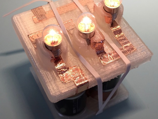
Comparing and contrasting series and parallel circuits shouldn’t be limited to LEDs, Christmas lights, and alligator clips. This #ScienceProject uses automotive lamps, C-sized batteries, and conductive tape to build compact demonstration stations for series and parallel circuits. This project requires: 6 Volt miniature light bulbs like these for the Parallel Circuit 1.5 Volt miniature light bulbs like these for the Series Circuit Double sided conductive copper tape like this 4 C batteries for each setup. Print Settings Printer Brand: MakerBot Printer: MakerBot Replicator Mini Rafts: Yes Supports: No Notes: Each of these pieces take between one and two hours to print. I designed them to fit on the #MakerBot Mini for those of us who don't have a lot of space in our labs. I’ve provided Mesh Mixer versions of the lamp bases, which work well with the Mini, but if you prefer not to use Mesh Mixer, I've also included un-supported versions of the files.The . If you choose to print those, be sure to clear all flashing out of the lamp holes, or they will not fit and you will not have a closed circuit. The top of the battery holder is designed to snap inside the lamp holder pieces. If you want to do more than one lamp holder, you'll need to do more than one top of the battery holder as well. Post-Printing Finishing work The parts of this project use conductive copper tape to make working circuits. The battery base and battery top have been designed to allow for a series connection of the batteries (quadrupling the voltage but maintaining the current). To configure your battery plates, place the copper tape as you see below. (In case your students get confused, the bottom plate is thicker than the top and has all the copper self contained. The upper plate is thinner and the copper wraps around to the top at the two sides. You can trace the path the electrons will follow as they happily march through the batteries, into your circuit, and back again. When laying the conductive path for the lamps, remember that the side of the lamp (where the thread is for screwing it in to a base) should be connected to one end of the circuit and the very bottom of the lamp (the silver protrusion at the base) connects to the other end. When applying the tape to the lamp holders, one piece should be laid inside the curve, overlapping to the outside, where it can connect to the rest of the circuit. The other piece should be laid flat inside the square groove at the base of the lamp holder, extending out the other side towards the other half of the circuit. Make sure the copper tape inside the lamp holders does not connect. The top of the battery holder is designed to snap inside the lamp holder base. It will not come out again, so make sure you've printed as many tops for the batteries as you've printed lamp holders. Once you've snapped them together, use the conductive tape to connect the circuit from the battery top to the lamp holder. Using the conductive tape, make the circuits you want to investigate on the surface of the lamp holder pieces. Remember, if using the parallel configuration, use the bulbs that can take the voltage. The 6 V bulbs are needed for the parallel circuit. The 1.5 to 2.5 V bulbs would be fine with the series circuit. Once assembled, you may have to increase the thickness of the copper in some spots or use a rubber band to provide tension - batteries have a bit of a difference in length and that can make all the difference in your project lighting up. Or not. How I Designed This This project was designed on #Autodesk #Inventor. The lamp holders are designed to hold your standard vehicle light bulb. In the Parallel layout, I added trace lines for students to lay the conductive tape but for the Series, I left the surface smooth for them to determine their own path. The battery plates are made to connect the batteries in series, with two traces leading out to connect to the lamp plate that gets snapped on to the top battery plate. Because of the differences in battery sizes, you may need to add a layer or two of the conductive tape to make sure each has a solid connection. Also, adding a rubber band to maintain a squeeze on the system will improve connectivity while also holding your projects together. Overview and Background Current and voltage directly influence the brightness of a light bulb. However, current and voltage are directly impacted by the arrangement of those light bulbs. In a series circuit, all bulbs will experience the same amount of current but the same cannot be said for a parallel circuit. The voltage drop across the bulbs will also be different, and in the case of the parallel circuit, can change if a bulb is removed. In this project, students can use these compact light stations to experiment with, measure, and observe the differences between parallel and series circuits. Lesson Plan and Activity These lamp holders make it possible for students to quickly and easily observe the effects of changing voltage, arrangement, and resistance on the circuit. Students should be introduced to the theory of DC circuits and Kirchhoff’s laws prior to activities, either through lecture or flipping the classroom. This is a great introduction that even features immediate feedback on formative assessment questions. Teachers could allow up to five hours of class time for this activity. In AP Physics, students are asked to craft their own laboratory investigations and should be asked questions that guide their investigation. For example: Is the current through a parallel circuit the same as that of a series circuit? How does the output of the circuit change when you change the number of lamps or the resistivity of those lamps? How do different arrangements of series and parallel circuits impact the brightness of the lamps? To initiate the project, allow students to assemble their lamp holders and “play around.” Once they’ve settled in, begin asking them if they feel the equipment is showing them what they think they should see, based on their prior learning. Encourage a class discussion on what they are seeing, what they’d like to see, and how they could accomplish that. Through this discussion, steer them towards the question at hand, then guide them towards writing the question and hypothesis, then allow them to spend some time developing a procedure and carrying out the remainder of the lab. The AP Physics Lab Manual has a great lab that the students can replicate with appropriate use of the conductive tape. As the students conduct their investigations, they should be following the scientific method:Observe the circuits and their behavior under varying conditionsResearch the concepts that apply to these behaviorsQuestion what the circuits would do under very specific conditionsHypothesize what the result would be, based on the observations and research conductedDevelop a laboratory investigation to collect data that would help test the hypothesisCollect and analyze data while conducting the laboratory investigationDraw conclusions, evaluate error, and project future investigationsCommunicate results Rubric and Assessment Students will develop a lab report that includes statement of problem, hypothesis, background, procedure, data table, graph of data, data analysis, error analysis, and conclusion. They can communicate this information with a presentation, poster session, or through a written report, depending on your preferences. References http://www.regentsprep.org/regents/physics/phys-topic.cfm?Course=PHYS&TopicCode=03bhttps://www.physics.byu.edu/faculty/rees/220/book/Lesson4.pdfhttps://secure-media.collegeboard.org/digitalServices/pdf/ap/ap-physics-inquiry-based-lab-manual.pdf To use this in your classroom Project Name Series and Parallel Lamp Holders for Physics Investigations Objectives After completing this activity, students will be able to qualitatively and quantitatively explain the difference between series and parallel circuits; the voltage, current, and resistance of their light stations; and how various changes to their light stations would impact the brightness of the bulbs. Standards NGSS 4-PS3-4. Apply scientific ideas to design, test, and refine a device that converts energy from one form to another. College Board Standards for AP Physics: Big Idea 1 - Objects and Systems have properties such as mass and charge. Systems may have internal structure. Enduring Understanding 1.E: Materials have many macroscopic properties that result from the arrangement and interactions of the atoms and molecules that make up the material. Essential Knowledge 1.e.2: Matter has a property called resistivity. Big Idea 3 - The interactions of an object with other objects can be described by forces. Enduring Understanding 3.C: At the macroscopic level, forces can be categorized as either long-range (action-at-a-distance) forces or contact forces. Essential Knowledge 3.c.2: electrical force results from the interaction of one object that has an electric charge with another object that has an electric charge. Big Idea 5 - Changes that occur as a result of interactions are constrained by conservation laws. Enduring Understanding 5.B: The energy of a system is conserved. Essential Knowledge 5.b.9: kirchhoff’s loop rule describes the conservation of energy in electrical circuits. Enduring Understanding 5.C: The electric charge of a system is conserved. Essential Knowledge 5.c.3: Kirchhoff’s junction rule describes the conservation of electric charge in electrical circuits. since charge is conserved, current must be conserved at each junction in the circuit. examples include circuits that combine resistors in series and parallel, with at most one parallel branch and one battery.
With this file you will be able to print Series and Parallel Circuit Lamp Holders with your 3D printer. Click on the button and save the file on your computer to work, edit or customize your design. You can also find more 3D designs for printers on Series and Parallel Circuit Lamp Holders.