SFX Bench Power Supply (Variable Voltage)
thingiverse
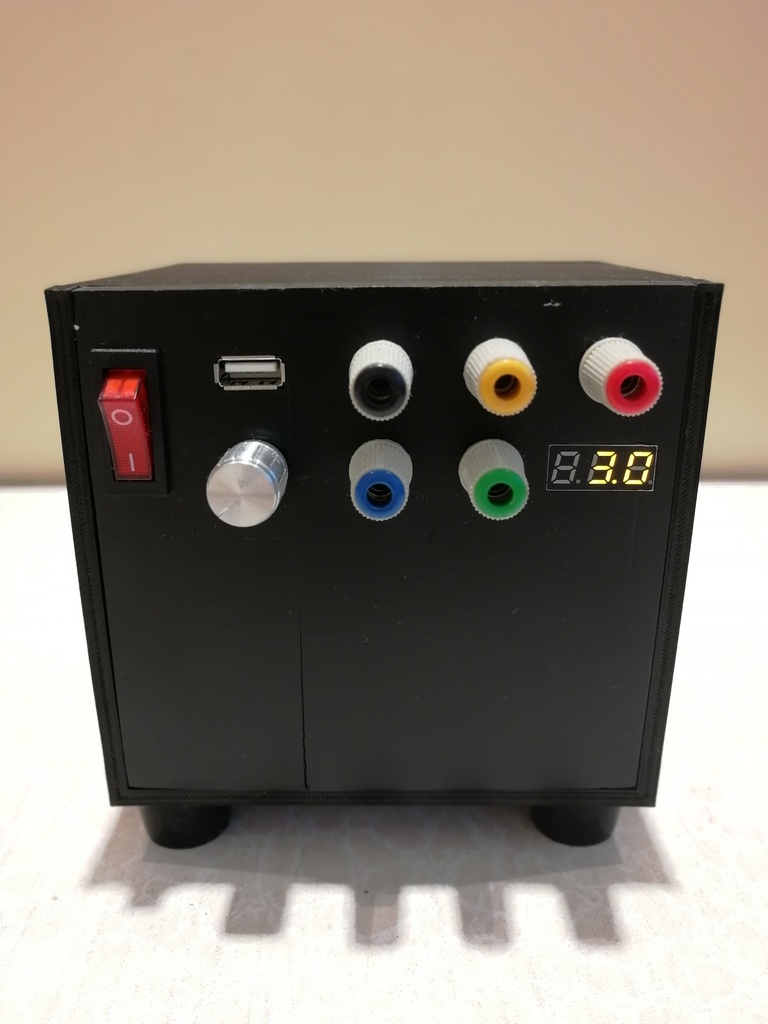
After scouring numerous tutorials on converting an ATX power supply into a variable voltage power supply, I concluded that most of them were overly complicated and included circuit diagrams that baffled me as a novice. My goal here is to provide clear instructions that anyone can follow. Please be aware that you're working with electricity, which requires extreme caution. Unplug everything before attempting to cut or solder wires, and take note that capacitors inside a power supply can store high voltages for an extended period after the power supply has been switched off. Proceed at your own risk; I won't be held liable for any accidents. You don't need to open the power supply for this build, so as long as you unplug it before tinkering, you should be fine. Remember to cut unnecessary wires and insulate them properly. Regarding the circuit: This is the simplest method I've found to output a variable voltage of 0-24v (or close enough) using a 12v line and a -12v line from the power supply. I'm not an electrician; I'm a designer and maker. If you're aware of any safety concerns or have a more straightforward way to achieve this, please comment and suggest changes. Ensure your power supply has a -12v line for this setup to work. The variable voltage banana sockets provide a voltage difference of 1.2v to 22.7v, which is suitable for most Arduino projects and similar applications. The circuit also includes USB, banana, and other sockets that deliver various voltages: 5v, 3.3v, and 5v. Bill of materials: Printed: 1 x CASE MAIN 1 x CASE FACE Bought: 5 x Banana sockets of different colors (https://item.taobao.com/item.htm?spm=a1z09.2.0.0.67002e8dUgkbaW&id=561956389062&_u=52q9f1426ddc) 1 x Potentiometer 50k Ohms (https://item.taobao.com/item.htm?spm=a1z09.2.0.0.67002e8dUgkbaW&id=13300625190&_u=52q9f1423320) 1 x Knob for the Potentiometer (https://item.taobao.com/item.htm?spm=a1z09.2.0.0.67002e8dUgkbaW&id=546066796422&_u=52q9f1422257) 1 x Switch (https://item.taobao.com/item.htm?spm=a1z09.2.0.0.67002e8dUgkbaW&id=560730371702&_u=52q9f1425c4f) 1 x Female USB Socket (https://item.taobao.com/item.htm?spm=a1z09.2.0.0.67002e8dUgkbaW&id=14422856956&_u=52q9f1428c5a) 1 x LED Voltage Display (0.28") (https://item.taobao.com/item.htm?spm=a1z09.2.0.0.67002e8dUgkbaW&id=544408516843&_u=52q9f1423bb7) 1 x SFX Power Supply (Bought a second-hand one on the street) 4 x 10-16mm M4 Screws for the face 7 x 10-12mm M4 Screws for the feet and the back of the SFX power supply 1 x LM317T Voltage Regulator 1 x Heat Sink for the regulator (I used the heat sink that came with the stock Anet A8) 1 x 120 Ohm resistor 1 x small protoboard Circuit: Assembling the components should be relatively straightforward, except for the wiring. Check the images for a wiring diagram I made in illustrator. I chose to show the circuit in this format rather than using Eagle CAD as it's easier for novices to understand. Make the circuit first and test it before assembling everything. If you're resting the protoboard on top of the power supply case, ensure the circuit is insulated from the metal case (I used hot glue for this). The circuit I created doesn't light up the switch when it's on, as I couldn't figure out how to do this. My switch likely requires 250v AC to light up; I'm unsure. The LED display lights up when the unit is on, which is good enough for me.
With this file you will be able to print SFX Bench Power Supply (Variable Voltage) with your 3D printer. Click on the button and save the file on your computer to work, edit or customize your design. You can also find more 3D designs for printers on SFX Bench Power Supply (Variable Voltage).