Silent Anet A8 Electronics Case Cover OctoPrint Raspberry Pi Zero W 4 Channel Relay Enclosure
thingiverse
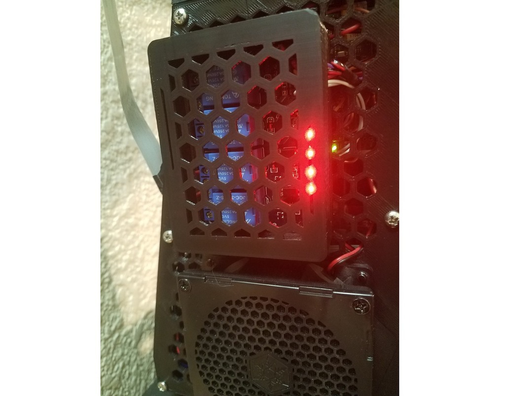
Here is the modified text: This custom case cover accommodates a 4-channel relay board that I control using a Raspberry Pi Zero W running OctoPrint. The original design was intended for the larger Pi2 but two of the holes align perfectly with the Pi Zero W, leaving some extra room for cables and connectors. To drive the relay module, you need to create custom circuits because the Pi's IO ports are 3.3V while the relay board requires 5V. This was a simple and inexpensive solution. The purpose of the relays is to use OctoPrint event functionality to turn on and off a loud fan situated on the extruder heat sink and the case fan, making the printer completely silent when it's not printing. I also plan to utilize one relay for a software-controlled emergency kill switch to add more safety features to the printer, and another relay to turn on large LED modules for time-lapse photography. Additionally, I'm driving RGB LED strips using the Raspberry Pi Zero but don't require relays for that. The original design is nearly perfect; I only added 1MM to the bottom and left side of the cover to make it stronger. The screw holes were close to the edge, and one corner broke on the original case. I used the bumper design to obtain the base measurements (my caliper battery died, so I couldn't get precise measurements). The bumper needed to be scaled up about 2MM to compensate for shrinkage. Printing it at 100% made it difficult to insert the board, and it was impossible to remove without damaging the bumper. This article helped me a lot in setting up the relay with my Pi Zero W: everything matched the Pi2 setup described in the article. It shows you the Raspberry Pi pinout and how to hook up the step-up adapters to the relay board. https://myhydropi.com/connecting-a-relay-board-to-a-raspberry-pi I used this relay board: https://amzn.to/2GOTkhw To create the driver circuit, you'll need a soldering iron, some solder, and something to shrink tubing with. Here's a step-by-step guide: 1. Bend the two outer legs of the transistor towards its flat part. 2. Solder a full-length 10K resistor to the Emitter leg; this will be connected to ground. 3. Cut the middle leg (Base) to about the length of the body of the 10K resistor. Cut one side of a 2.2K resistor to the same length. 4. Solder the two ends together. 5. Allow solder to cool and slide a 3MM shrink tube onto this joint. 6. Using needle-nose pliers, make two bends on the other end of the 2.2K resistor so that it's parallel to the 10K resistor and solder them together. 7. Trim all ends to about 1/4 inch or whatever you feel comfortable soldering a piece of wire to. 8. Clean up the solder joints but leave some extra solder on them for a good bond with the wire. 9. Slip on 3MM tube onto the wire, then solder it with the dupont connector and shrink tube around the joint. 10. Slide 3MM shrink wrap around two remaining wires: one with a dupont connector for the relay pin and another to the ground connector on the Raspberry Pi and the relay board (you'll need to create a harness with multiple ground wires connected together). For the software configuration portion: You'll need to copy the attached on.py and off.py Python scripts to the pi user's home directory to use this setup. OctoPrint events configuration section (add this to the end, also attached with the right formatting): events: enabled: true subscriptions: - event: PrintStarted command: python ~/on.py type: system - event: PrintDone command: python ~/off.py type: system - event: PrintFailed command: python ~/off.py type: system - event: PrintCancelled command: python ~/off.py type: system I tried using some of the OctoPi images but encountered issues with SSH and other problems, so I built my own OctoPrint from a clean Raspbian install.
With this file you will be able to print Silent Anet A8 Electronics Case Cover OctoPrint Raspberry Pi Zero W 4 Channel Relay Enclosure with your 3D printer. Click on the button and save the file on your computer to work, edit or customize your design. You can also find more 3D designs for printers on Silent Anet A8 Electronics Case Cover OctoPrint Raspberry Pi Zero W 4 Channel Relay Enclosure.