Sim Racing Hand Brake
thingiverse
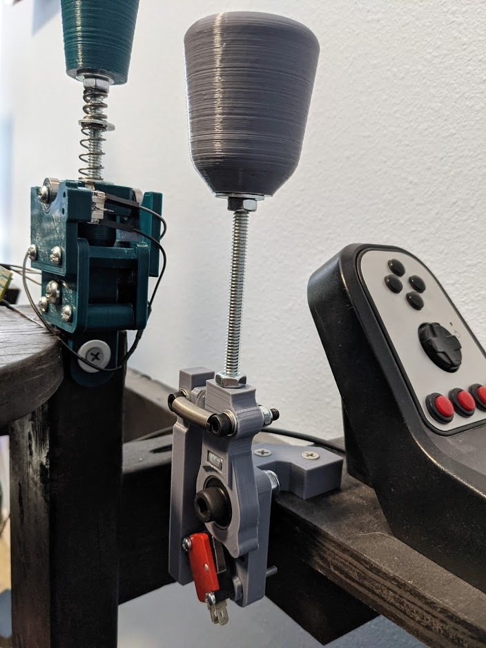
I designed this as a handbrake for racing sims where you only need momentary braking without a ratcheting mechanism, like drifting. You can probably use this for a lot of other functions since it's just a simple switch. My favorite examples (off the top of my head): - Arm to deploy parachutes or other single-use functions - Rocket boost lever - A lever for your evil henchmen - Cookie dispenser - Vegetable dispenser The arm will rotate about 45 degrees before it hits the switch. Since I am in the US, and it's easy and cheap to find inch sized fasteners, the arm's shaft is a 1/4" threaded rod. All other fasteners were designed as metric fitment. I did include a couple extra versions of shaft pieces to help use a metric threaded rod. Here is a list of the parts and what you can use instead: - Arm frame - this is the base for everything, and is common for all parts - Bearing Pivot - three provided, all use the same bearing, but there are three versions with the appropriate hole and square nut cutout for your threaded rod of choice. Make sure you print the flat side down. Note that the bearing will press in from the side that faces up when printed flat side down. There is a little lip to stop the bearing once it's pressed in. - Knob - just a simple grip knob, again three versions for your threaded rod (this is a good simple part to get your feet wet in design if you want to make it your own - it has no impact on the performance besides how it feels in your hand). A locking nut fits in the top, and I used a washer and nut to jam against the bottom to keep it from wanting to spin. - Spring block - only two of these, since the 1/4" and M6 are able to both use the same one. This slides down the rod to hold a bolt for the springs which go on either side. - Switch spacer - make sure you print 2! common for all parts. Just some simple spacers to locate your switch appropriately. The hardware you'll need: - qty. 1 of M8, M6, or 1/4" threaded rod - I used a 6.5" / ~165mm length, but feel free to use one longer or shorter for personal preference - qty. 2 of M8, M6, or 1/4" regular hex nuts - These go on the arm shaft, and are to jam against the spring block and knob and keep them from wobbling or walking around. - qty. 1 of M8, M6, or 1/4" locking nut - I prefer this on the top of the knob to help keep it from loosening and James Hunt Japan 1976'ing you. - qty. 1 of M8, M6, or 1/4" square nut - This goes in the rectangle cutout in the pivot. The sizes are 13mm, 10mm, and 7/16", respective to the given shaft size. There is a bit of tolerance built into this to make it a tight fit with respect to the slight shrinkage that happens in 3D printing. Be prepared to use clamps to squeeze the nut into place. Mine was able to just push in with my thumb. - qty. 2 of coil springs - I found two in a pack of random springs I got at Home Depot, they have the ends bent so that the last couple coils make for loops you can put bolts through. Mine measure roughly 33mm center-to-center of those end loops. You should have some freedom to use a lot of different springs here, as long as they fit. - qty. 2 of M5 x 25mm bolts, w/ locking nuts and washers - These hold the springs in place. I used locking nuts so I didn't have to fully cinch the springs down (allows them to pivot), but the bolt won't loosen over time. - qty. 2 of M3 x 30 mm bolts w/ locking nuts - These hold the switch down, with the two spacers sandwiched between the switch and frame upright - qty. 1 of momentary microswitch - Make sure you can use 3mm bolts through it, and make sure it fits. I used switch # V-153-1V25 that I had on hand, but I gave the frame long slots for the mounting bolts to allow some freedom. You can also print more spacers to stack up and space the switch you use if it's narrower than 10 mm. - qty. 1 of M8 x 30 bolt w/ washer and locking nut - For mounting the bearing to the frame and acting as the axle. Put the washer on the nut side on the back, so that it doesn't interfere with the bearing, and also to spread the load on the plastic better - qty. 1 of 608-2RS (or equivalent size) ball bearing - Pretty self explanatory. Another press fit, so keep the clamps out. A nut or washer works well to push it down against the little stop built in - qty. 2 of screws to fasten to your surface - I'm leaving this one open ended for requirements since it will have to be tailored to your surface. I am using American #8 wood screws, but any flat head (bugle shaped) machine screw would also work if you want to bolt it down instead. IMPORTANT: because of how the layers print, make sure you drill the holes to allow your screw to push through by hand. If you don't, the layers can easily split at the screw, and you'll have to wait for a new frame to print. Ask me how I know. - a small cabinet bumper - this fits on the pad behind the spring block on the frame. Keeps the noise and damage down. I think assembly is pretty straight forward, just use the reference image. You're on your own for wiring and making it work with your computer. There are guides on the internet that would do a much better job than I. Your choice of Teensy or Arduino or similar should work great. The green sequential shifter in the photos is this one by bardocz: https://www.thingiverse.com/thing:4078775 Good luck, and happy racing/parachuting/blasting/evil/cookies/gross veggies!
With this file you will be able to print Sim Racing Hand Brake with your 3D printer. Click on the button and save the file on your computer to work, edit or customize your design. You can also find more 3D designs for printers on Sim Racing Hand Brake.