Simple and Accurate Crown Gear (or Hirth Joint) in FreeCAD
thingiverse
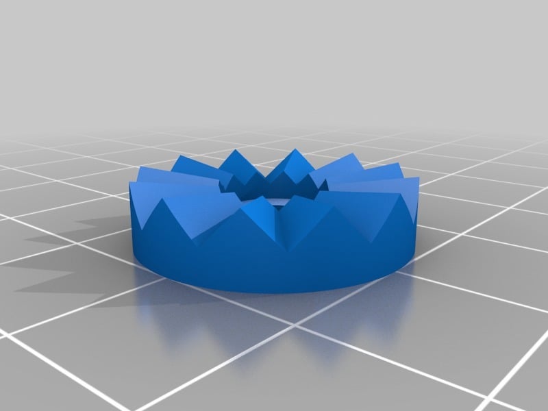
Rather than Customizing an existing design, you can use these procedures to embed a Crown Gear (also called a Hirth Joint) in your own design. The resulting gear can be fused, cut, and intersected with other shapes. All tooth edges are coincident to a single point at center. All surfaces are planar to ensure the tooth angle with respect to the axis is consistent throughout the length of each tooth. 1. Create a sketch in the XZ-plane for the cross section of a cylinder. Add shoulders as necessary to support recessed screws, etc. 2. Revolve this sketch into a wedge. Choose an angle such that its product with an even number is 360; for example,15 x 24 = 360. 3. Create a sketch on the outside surface of wedge. Use the side edges of wedge as reference geometry. Set the angle of the top edge to desired angle of gear tooth. Only draw half of a tooth. 4. Extrude the new sketch. Set "Along" to a small amount. Set "Against" to radius of final gear. 5. Use Common Tool to intersect the two shapes. 6. Create a mirror of Common shape in the XZ-plane. 7. Fuse the Common shape with its Mirror. 8. Create an Array in Draft Workbench. Set "Fused" = true. Set "Array Type" = Polar. The result is a gear that can be rotated and translated anywhere in the overall design by changing its "Base Placement" properties. Revised May 31st, 2018 New procedures that allow precise control over angle of gear teeth.
With this file you will be able to print Simple and Accurate Crown Gear (or Hirth Joint) in FreeCAD with your 3D printer. Click on the button and save the file on your computer to work, edit or customize your design. You can also find more 3D designs for printers on Simple and Accurate Crown Gear (or Hirth Joint) in FreeCAD.