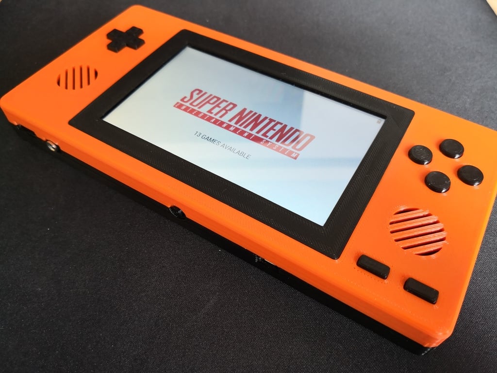
simplyRetro Z5 ( RetroPie / Emulation handheld )
thingiverse
It seems like you've provided a detailed guide on how to use a custom distribution called "simplyRetro-Z5" for playing retro games on an embedded device, specifically the Z5. This distribution is built on top of BuildRoot and includes the necessary packages for emulating various classic game consoles and systems. Here's a breakdown of the key points: 1. **Custom Distribution**: The simplyRetro-Z5 distribution can be downloaded from GitHub. It's based on BuildRoot and contains only the required packages for playing games on the Z5. 2. **Supported Systems**: The distribution currently supports Arcade (MAME2013-plus), Gameboy DMG/Color, Gameboy Advance, NES, SNES, Meda Drive/Master System/Sega CD. 3. **Boot Partition**: The SD Card is divided into two partitions: one for the boot process and another for storing data. The `config.txt` file configures the screen rotation, while `retrogame.cfg` sets up the controller settings, and `retropower.cfg` configures the power-off button. 4. **Login**: To access the system, use the default credentials: user `root` with password `simplyretro`. 5. **Resize Root**: To utilize the full capacity of the SD Card, run the `/root/reformat.sh` and `/root/resize.sh` scripts in sequence. 6. **WiFi, FTP & SSH**: Set up WiFi, FTP, or SSH services through the EmulationStation menu after configuring your network settings. 7. **ROMs and BIOS folder**: Store ROMs and BIOS files at `*/root/roms*` and `*/root/bios*`, respectively. 8. **Controls**: Configure your controller in EmulationStation, use `START + B` to exit a game, and `START + A` to open the Retro Arch menu while playing. This guide provides detailed instructions for users who want to set up their Z5 device with the simplyRetro-Z5 distribution.
With this file you will be able to print simplyRetro Z5 ( RetroPie / Emulation handheld ) with your 3D printer. Click on the button and save the file on your computer to work, edit or customize your design. You can also find more 3D designs for printers on simplyRetro Z5 ( RetroPie / Emulation handheld ).