SketchUp for all lead-screw cube
thingiverse
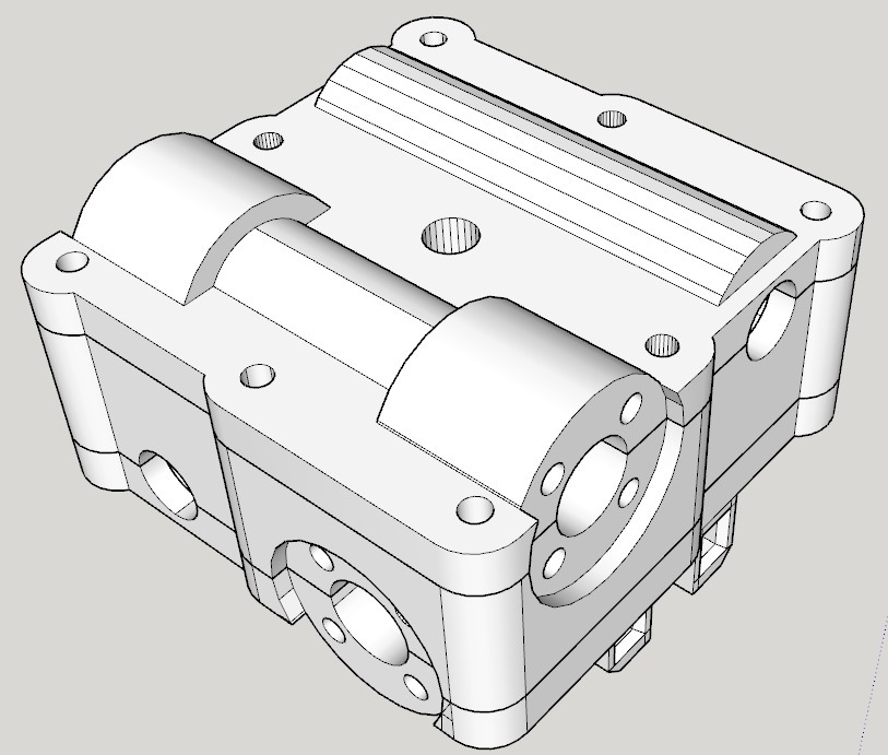
** Update: 08/22/2017 I still have some parts coming so it's not fully assembled, but I have included a few phone camera snapshots of my build in progress! Only a few more parts and I can work on the wiring. After all that's done, it'll be on to motion tests and I hope to post some video of each axis is motion. Please forgive the dirty hot-end - I am just test-fitting all the parts - it'll get a clean, shiny hot end when it's time to start printing. If all works well, I will replace the Nema 17 motors, couplers, and lead screws with motor\lead screw integrated combos - that should give me an extra 3-4 cm on both the X and Y axis. ** Update: 08/21/2017 I have uploaded a 3-part XY Carriage block for this printer. I removed as much excess plastic as possible to keep the bulk and weight down. Use any of the various shims on the 2nd TR8x8 nut because it can't sit flat against the XY Carriage AND line up with the holes - once you look at or print out the model, you will understand. ** The hardest part about this XY Carriage is that, because it will hold the hot end, it needs to resist heat - and for me that means ABS, Keeping the edges flat is a challenge, so consult whatever resources you deem necessary to help you get the best quality\least warping when printing these parts. I also added in my current models for the motor and idler ends of the X and Y axis as well as new top-mount corners which hold the X and Y axis rods along which the ends travel. I have always been fascinated by XY carriages that don't use timing belts but instead use lead screws, and the thing I have listed as the remix source has been the closest I have found to it. There is an all lead screw Cartesian printer called the ScrewRap (http://reprap.org/wiki/ScrewRap) but I wanted a cube configuration for stability. That thing, however, only includes a few parts and it only has external images - excluding the all-important placement of the lead screw nuts in the XY carriage! I resized the motor and idler objects so they use lm8uu bearings instead of the 10mm linear bearings AND I resized the other bearings to now use 608 skate bearings (22mm x 8mm with 8mm spinning hole). I treated this like a puzzle and used the pieces in that thing to try to mock up what the full printer would look like, but I still don't see where in the XY carriage I would put the nuts that attach it to the x and y lead screws. I have uploaded my SketchUp file and I hope anyone else who might be interested will help me improve it AND, more importantly for the moment, help me figure out where the lead screw nuts go inside the x y carriage. Please and thank you in advance! :)
With this file you will be able to print SketchUp for all lead-screw cube with your 3D printer. Click on the button and save the file on your computer to work, edit or customize your design. You can also find more 3D designs for printers on SketchUp for all lead-screw cube.