SLAM/GPS 4WD Offroad robotic experimental platform
thingiverse
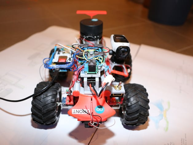
This is a large (2.5kg with hardware, ~504030 cm) all wheel drive 'platform' for GPS/SLAM experimentation. There is some footage of it using GPS to navigate here: http://youtu.be/Q1CUnUzaENc and using LIDAR to avoid obstacles (but not phone cameras) here: http://youtu.be/v2fPF3EMCtM The EOP is designed to: be printed on a printer with build volume 140mm width, 140mm depth, 135mm height i.e. Up Plus, makerbot or most hobby printers should suffice, but you know the limits of your own printer!!! to be very flexible. there is a basic chassis. Parts click on and off (mostly - some need bolts and nuts) and you can add or modify the accessories (LCD, breakout boards, gopro/virb mount etc) and suspension. uses skid steer (see motor/battery/relay combination I use below to make this work at this weight). It works very well - will climb until it flips over. I have included the CAD file (rhino .3dm) to aid modification (UPDATED 13OCT2014). Instructions I can't help you with coding or wiring right now. I will upload better assembly instructions later. For now there's photos!!!! IMPORTANT NOTE 1: the suspension braces and 'motor stiffening' (1 rear, 1 front, = bracing between 2 motors) are critical pieces. They are all essential if you don't want it to fold in half! IMPORTANT NOTE 2: you have to print 3 x the chassis member, then glue this together. I sanded mine to make the faces perfectly flat. If you do this right it will be strong enough. The plastic will break before the joint. THE REST: It does print easily. I needed no special tricks, but suggest you print the 'working' surfaces of the suspension facing up so they will be smooth and precise as possible. The base design has Arduino standard sized carriers and a carrier for an accessible Lidar, but I've included the rhino .3dm so you can change any part to suit your hardware. Some glueing and drilling and screwing is required. SMALL PROBLEM: The side carrier that is needed to fit the longer Mega Arduino is too big to print on my printer (the original for an 'Uno' lets the corners of the Mega just touch the wheels at max. axle articulation). THE FIX: get a bigger printer, or, you can use a heat gun to adjust the inclination of your the arduino side carriers to suit the Mega. How? Set the hot air gun to 250 degrees (or guess if you can;t do that), put a blank proto shield in the carrier to make the receiver hold its shape, heat the place you want to bend (around 10-15 secs should do - it goes shiny), then bend to suit the angle you need. Yes, this does work! See Photo. Here's the hardware I have on my prototype: Arduino Mega Compass/Accel: Adafruit Triple-axis Accelerometer+Magnetometer (Compass) Board - LSM303 LCD: Adafruit ST7735 Motors: 04 x MEC-30090 : 75:1 Metal Gearmotor 25Dx54L mm Motor brackets aluminium: 2 x Pololu 25D mm Metal Gearmotor Bracket Pair Relays: MCU-60121 Pololu Basic SPDT Relay Carrier with 12VDC Battery: NiMh 6.2V GPS: GPS Shield with SD card socket for Arduino PS_SDV2B_P3 Cliff detection: 4 x IR distance sensor (
With this file you will be able to print SLAM/GPS 4WD Offroad robotic experimental platform with your 3D printer. Click on the button and save the file on your computer to work, edit or customize your design. You can also find more 3D designs for printers on SLAM/GPS 4WD Offroad robotic experimental platform.