Smart Voltmeter Data Logger Hex Calculator Arduino Instrument
thingiverse
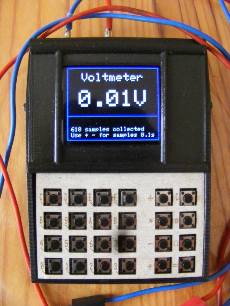
Description : See: https://github.com/boda-akos/STM32-Voltmeter-Data-Logger-Calculator This instrument has some useful functions for Arduino users. Besides being a voltmeter with data logging, it could answer questions like "how much voltage falls on the LED at 10mA current?" or "is this an IR LED or what?" by showing the diode's voltage drop as a function of current at 5 points. It has a beeper for continuity check as well as for logic level testing, without the need to look at the display. Furthermore, it can play 3 octaves "musical pitch" as a function of voltage, which could be useful when the question arises "is there 5V, 12V, or nothing?" but you have to keep your eyes on the PCB. Hex calculator 32 bits has the basic integer arithmetic functions plus AND. Entered hex numbers are shown at the same time in decimal in smaller numbers. This can be reversed so that the input is decimal and the result is decimal too and the hex numbers are smaller. Operates 10-20 hours with one battery charge. Functions : 1. 12-bit resolution voltmeter auto-ranging 0-3V 0-31V Input impedance 11.2 Mohm or more. Accuracy depends on some factors, about 1%. Specials : - Data logging at 100ms or 1 sec intervals, max. 3600 FP data. - 3 octave pitch to estimate 0-31V voltage without looking - Beep function to test logic level without looking 2. Continuity tester (1mA current) 3. Curve draw for diodes 0.1-0.3-1-3-10 mA current 0-3V voltage 4. Hex calculator, only integers, + - / * & (AND) function. Shows operators and results in decimal at the same time. 5. Decimal calculator, only integers. Shows HEX results as well. Power : Li-Ion battery with USB charger. Dimensions : approx. 70x100x25mm. Main parts : STM32 Blue Pill board ST7735 SPI 1.77" LCD FPC version Micro USB Li-Ion charger PCB Phone battery 700mAh or more 16x 6mm switch array 2 pcs 2mm banana sockets Off-On-On slider switch Small (really small SMD) electronic parts Source : Aliexpress Circuit description : The battery is charged from micro USB by the TC4056A board. Voltage is fed to power switch, the 2 ON position of the switch selects calculator or voltmeter functions. The HT7333 regulator (replaces the built-in RT8183-B, or AMS1117) provides 3.3V from the battery 3.6-4.2V. The 3.3V supply is also the reference voltage for the STM32 A/D converter. Its value determines the accuracy, so it should be measured and entered in the code. (float vref=3.3; means 3.30V , enter your value if different by 1% or more) 1. Calculator : the STM32 scans the keyboard, decodes the keys and responds to it. The 0-F keys work in HEX input mode, the 0-9 keys in decimal mode. & key selects between hex or decimal mode, C key deletes the last entry, = key shows result. 2A. Voltmeter : This function is selected by the = key, default by start. The instrument shows 0 for negative input voltages, but no damage is done. (Update 27 oct. 2020 : Optional warning for negative input voltages, see below) The useful range is limited to approx. 31VDC. The data (3600 floating point Volts) is stored in RAM at 1 or 0.1s intervals. Key functions: Equal sign toggles 0.1 sec - 1 sec sample interval. Slash turns on octave pitch. Low C 131Hz at 0V, the range is divided in 21 steps so the max value corresponds to C 1044Hz 3 octaves higher. Asterisk turns on logic check. Low logic level : no sound, high >0.9V level 784Hz. C turns off sound Minus sign resets data log counter, fresh data starts from index = 0. Plus sign Enter data log mode, shows 50 data log, starting with recent voltage samples. In data log mode Plus sign advances 50 samples. Minus sign steps back 50 samples (older data). Equal sign returns to voltmeter mode, data collect resumes. Data index is shown so the user can determine when the data was collected. Data collection is halted in this mode. 2B. Continuity tester : This function is selected by the & key. The instrument outputs 1mA current and measures the voltage on its input. If the input < 100mV the beeper is activated. Higher input voltage does no harm, voltage is measured correctly. 2C. Diode curve draw : This function is selected by the # key. Current is output in 5 logarithmic steps 0.1, 0.3, 1, 3, 10mA and the resulting input voltage is displayed on a graph. The values are displayed in table form too. A resistor will obviously return a similar logarithmic voltage graph, but a diode's graph is almost linear. Some typical values in attachment. Analog circuit : is built on a perfboard 45x10mm. For connections 0.25mm enamel wire is used. The HT7333 regulator replaces the built-in RT8183-B, or AMS1117. The circuit is a low-res logarithmic D/A converter driving the current output. The current source has 5 resistors from which 4 are switched on by Mosfets. The current through the resistors drives the BCV62 current mirror, the common base is fed to PA2, which can disable the current mirror by pulling this point high, or could measure its voltage to calculate the exact current flowing through the resistors. The current mirror's output is separated by a diode from the voltmeter input as protection against high positive voltages. The voltage divider 10M/1.2M is connected to PA1 while a direct input is to PA0. Both are protected by resistors and diode network. A 100nF capacitor filters the input noise. Take care to use this ground point for the input ground, and feed it separately to the STM32 board to avoid ground loop issues. The board has a speaker driver, the 150ohm resistor controls the volume. Switch array : ready made 4x4 switch arrays, one cut in half. The 4 "horizontal" scan lines are parallel connected and fed to PB9,PB6,PB4,PC13 and the 6 "vertical" scan lines are driven by PB8,PB7,PB5,PB3,PA14,PA15. PB14 senses power switch position. LCD : 1.77” LCD has FPC 14 connection. I soldered 0.25mm enamel wire on the connector without difficulties. Backlight supply 3.3V serial 10 ohm resistor, current 35 mA. Update 27-oct-2020 : Negative voltage sense circuit is added, see the negSense.png schematics. This circuit and the corresponding code is optional. Do not use the code without the circuit. At negative input voltages a warning is displayed. The SI2301 P-MOSFET works in a very twisted way. Gate is connected to input with a 2M2 resistor in series. The SRV5-4 diode array protects it. The source is grounded, the drain gets a small (100mV) positive voltage. The internal diode does not open at this voltage, nor does the P-MOSFET conduct on zero or positive input. Should the input become negative, the P-MOSFET opens and pulls the drain to ground. PA3 checks this voltage and triggers a warning in this case. My instrument was triggered at 0.4V negative input. Change the code (starting from line 75) to activate the circuit ONLY if connected to PA3. Do not use this code snippet sketch_oct27a.ino without the circuit. -End of update 27 oct. 2020 ---------------------------------------------------------------------------- Do not attempt to measure AC voltage with this instrument, keep away from mains in particular !! Libraries : https://github.com/rogerclarkmelbourne/Arduino_STM32/wiki/Installation https://github.com/adafruit/Adafruit-ST7735-Library This object was made in Tinkercad. Edit it online https://www.tinkercad.com/things/eP8Pe3ALgYd
With this file you will be able to print Smart Voltmeter Data Logger Hex Calculator Arduino Instrument with your 3D printer. Click on the button and save the file on your computer to work, edit or customize your design. You can also find more 3D designs for printers on Smart Voltmeter Data Logger Hex Calculator Arduino Instrument.