Smarthome Ethernet to ESP8266 GPIO Concentrator
thingiverse
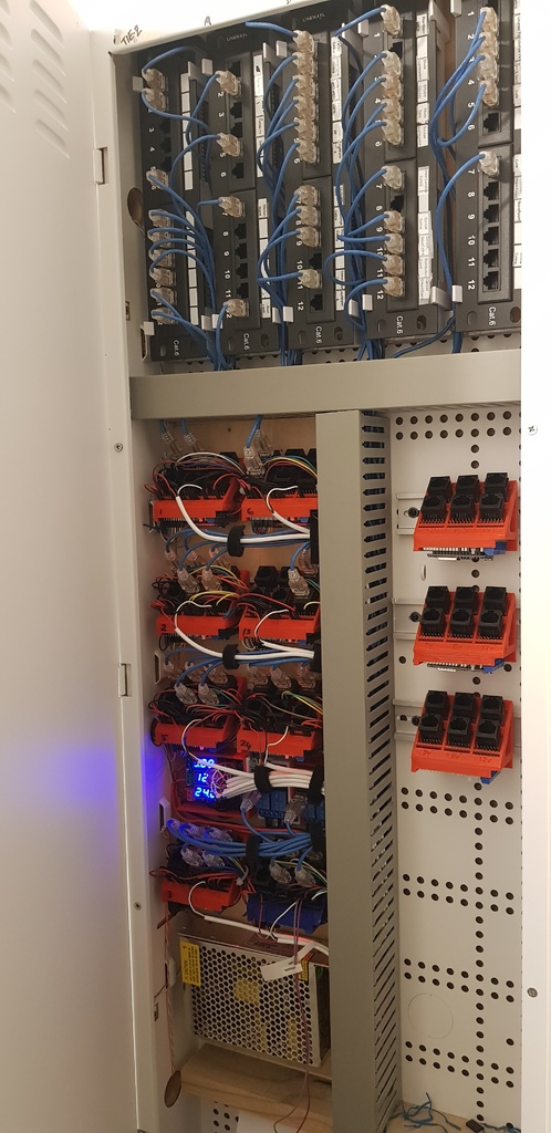
This thing holds six Ethernet RJ-45 connectors, an ESP8266 module and allows for three voltage busses. The idea is that with a lot of GPIO requirements in a DIY smart home system you need a scalable adjustable system to manage all those Ethernet cables and the hundreds of breakout cables. In my opinion, all smart homes will have a combination of one or multiple: - Input devices - sensors, switches, etc. - Output devices - relays, drivers, voltage, etc. - Connectivity options - wiring, wireless, power, etc. - An event bus - Openhab, IFTTT, raw code, etc. - A communication method - RS232, MQTT, HTTP API, etc. Recently, we built a new house with a DIY smart home capability. With so many different wiring models available (central switching, distributed switching, custom cabling, commercial solutions) we thought it essential to define goals before committing to a strategy. We knew that we wanted: - Use of inexpensive highly available input and output devices - Ability to add functionality over time - Ability to update technology over time - Ability to remove the solution if the house is sold and convert back to traditional wall switches - Reduce the chance of fire from transformers in the walls (110v/230v->5v = fire risk) - Maximise reliability and not having to fix prototype electronics all the time - Ability for some experimentation without breaking the bank - Minimise blast radius if the smoke comes out of something - Absolutely NOT rely on Google, or Amazon or any external internet connectivity to function - Not get locked into a single vendor solutions but ability to integrate if needed We managed to achieve all these goals and more. Our solution was to run a CAT-6 cable to every light switch, centre of every room, every door jam, every window, the distribution board, gate automation, irrigation controls, solar plant room, Security cameras and four cables at every TV location. All of these cables returned to a central location, well away from the power distribution board. In all about 3.5km of cat6 cable. 5v Sensors and relays are terminated to the cable with standard RJ45 plugs and hidden behind switches and wallplates (no transformers needed) and all power supply and GPIO is located centrally in standard (metal/fireproof) wall cabinets. Odroid single board computers run Openhab, Mycroft Zoneminder, Influx, Telegraf, and Grafana to capture and display historical data from all of the sensors. Mosquitto hosts the MQTT via wireless and 35 x ESP8266/NodeMCU/LUA with custom firmware provides all the GPIO. Commodity Opto-isolated relays do the switching at the wall switch or outlet and importantly can be removed later to revert back to traditional switching if the house is sold to a non SmartHome buyer. All that cable needed to be connected back to to the ESP8266's GPIO. This concentrator is how I consolidated the cat6 terminations (six at a time) to a single ESP8266. The house uses 35 x ESP's. The concentrator is designed to mount on din rail. Cables are punched down to a 12way patch, vertically mounted, six per wall cabinet and then patched through to the concentrator with micro patch cables. You will need additional: - Six RJ-45 180 degree connectors - https://www.aliexpress.com/item/32918645271.html - Six RJ-45 breakout board - https://www.aliexpress.com/item/33031656602.html - Single Row Male 2.54 Pin Headers - https://www.aliexpress.com/item/665534073.html - One NodeMCU Motor Board L293D - https://www.aliexpress.com/item/32957752310.html - One NodeMCU ESP8266 Dev board - https://www.aliexpress.com/item/32656775273.html Even for 35 of these, a new or retro smart home solution shouldn't be too expensive. (other than getting the cable into the walls). I'll be putting all the other bits used for this solution here as I get time. If you like please like if you build I'd be really keen to see what you have done. Happy to answer any questions via comments.
With this file you will be able to print Smarthome Ethernet to ESP8266 GPIO Concentrator with your 3D printer. Click on the button and save the file on your computer to work, edit or customize your design. You can also find more 3D designs for printers on Smarthome Ethernet to ESP8266 GPIO Concentrator.