Smarthome Multisensor V1
thingiverse
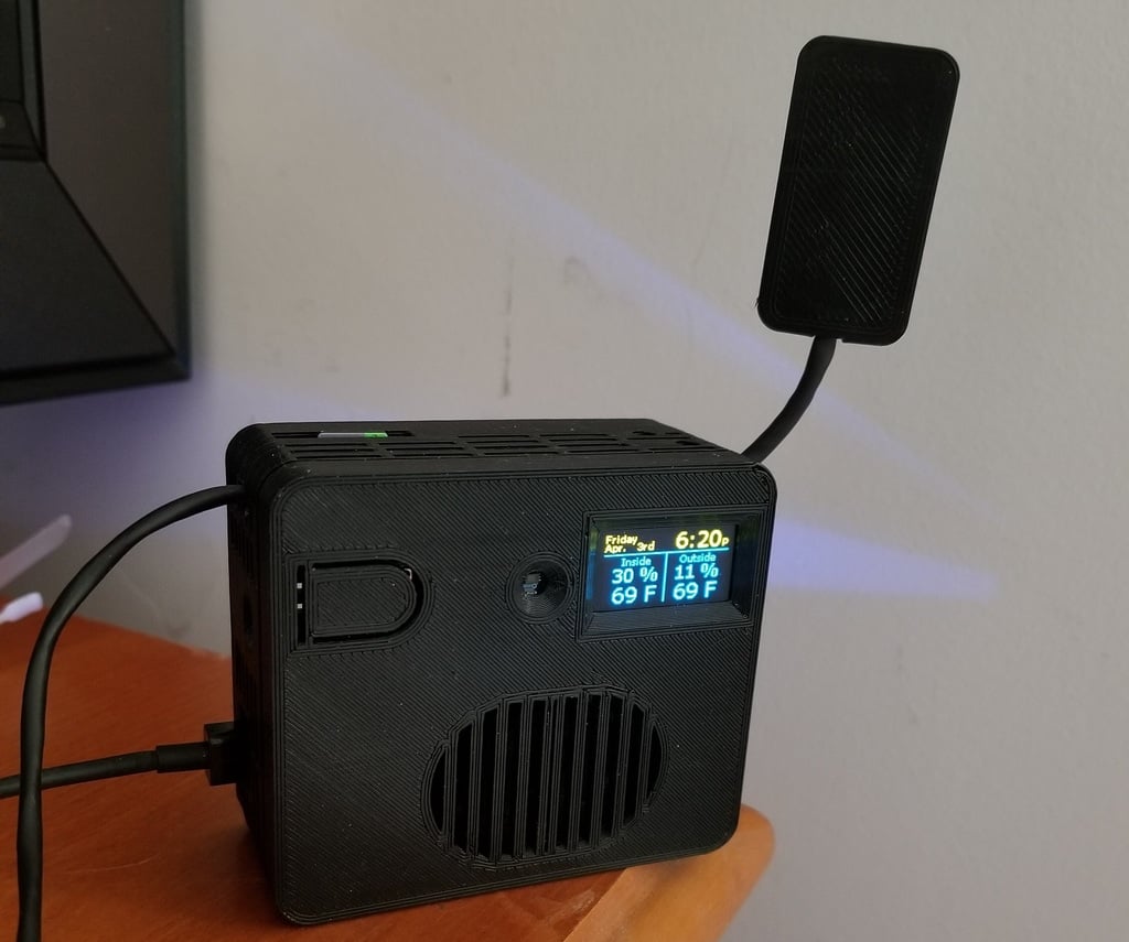
I designed this enclosure for an esp8266 powered all-in-one smarthome device. Here is the list of the parts I used in this project: Wemos D1 Mini: https://www.amazon.com/gp/product/B081PX9YFV/ref=ppx_yo_dt_b_asin_title_o06_s00?ie=UTF8&psc=1 SSD1306 64x128 OLED display: https://www.amazon.com/PEMENOL-Display-0-96inch-Raspberry-Microcontroller/dp/B07F3KY8NF/ref=sr_1_3?crid=3QXQAY17JCDZC&dchild=1&keywords=ssd1306+oled&qid=1585187363&sprefix=ssd13%2Caps%2C197&sr=8-3 12mm 5V buzzer (add a small NPN transistor or fet to drive it at 5V): https://www.amazon.com/gp/product/B01N7NHSY6/ref=ppx_yo_dt_b_asin_title_o01_s00?ie=UTF8&psc=1 AMS1117 3v3 supply: https://www.amazon.com/gp/product/B0778KR6FZ/ref=ppx_yo_dt_b_asin_title_o03_s01?ie=UTF8&psc=1 MT3608 DC-DC boost supply: https://www.amazon.com/gp/product/B081JJDD7J/ref=ppx_yo_dt_b_asin_title_o06_s00?ie=UTF8&psc=1 RCWL-0516 microwave motion sensor: https://www.amazon.com/RCWL-0516-Detection-Microwave-Detector-Distance/dp/B07MTWZDQZ/ref=sr_1_2?crid=MD3YKDT8XHET&dchild=1&keywords=rcwl-0516&qid=1585527400&sprefix=rcwl%2Caps%2C200&sr=8-2 BH1750 luminance sensor: https://www.amazon.com/HiLetgo-GY-302-BH1750-Intensity-Illumination/dp/B00M0F29OS/ref=sr_1_1?dchild=1&keywords=bh1750&qid=1585187244&sr=8-1 DHT22 humidity sensor: https://www.amazon.com/Aideepen-Digital-Temperature-Humidity-Replace/dp/B01IBBFOF0/ref=sr_1_8?dchild=1&keywords=dht22&qid=1585188263&sr=8-8 Dallas DS18B20 temperature sensor: https://www.amazon.com/DS18B20-Temperature-Raspberry-Separate-Antistatic/dp/B07STT9H74/ref=sr_1_2?dchild=1&keywords=dallas+temperature+sensor&qid=1585527304&sr=8-2 DFPlayer Mini: https://www.amazon.com/Anmbest-YX5200-DFPlayer-Supporting-Arduino/dp/B07JGWMPTF/ref=sr_1_2?dchild=1&keywords=dfplayer&qid=1585187409&sr=8-2 5W mini speaker: https://www.amazon.com/CQRobot-Speaker-Interface-Electronic-Projects/dp/B0822YL2L2/ref=sr_1_14?dchild=1&keywords=5w+speaker&qid=1585187457&sr=8-14 6x6x5mm momentary N/O button: https://www.amazon.com/Momentary-Tactile-Through-Breadboard-Friendly/dp/B07WF76VHT/ref=sr_1_5?dchild=1&keywords=6mm+button&qid=1585596563&sr=8-5 You could do whatever you want with this combo of hardware. I program these things using esphome for homeassistant. I use the OLED display to show date, time, inside/outside temp/humidity, etc, the sensors and button just report states to home assistant, and the dfplayer/speaker provide mp3 voice and beeper prompts/feedback for various automations I use. I use the step up converter to provide 12V to an optional external rcwl0516 microwave motion sensor (this sensor needs to be mounted away from wires & metal). I manually added supports for the longer bridges, so no supports should be necessary (my a8 prints this in abs @0.2mm no problem). The OLED screen, button mount (button simply presses into mount), speaker, and bh1750 go in the lid, the rest of the stuff goes in the main box. Except for the DHT and the beeper, all of the devices are secured with melt down pins and PCB rails. Press the part onto the pins/rails, heat a bolt or screwdriver and melt the pins/rails down against the board to fix them permanently. The beeper and dht are secured with a press fit. You can use a hot screwdriver or glue to secure them better if needed. Note that it is always easier to solder all wires to the boards first, before permanently mounting the boards in the box. The square hole on the left side is sized to fit the largest micro USB end I had on hand; it should fit most cords you might use. Wires for the rcwl & dallas sensors may pass through the 4mm holes located on the left, right, back, and/or bottom sides (note these 2 devices are best mounted away from the heat and interference emitted from the main enclosure). 2 access holes are placed on the front and rear of the box to access the MT3608 adjust pot and the wemos reset button. Another access hole in the back allows external access to the micro sd card for the dfplayer. A side note on wiring... There are many ways to wire the power to all the devices. To maximize efficiency and reduce noise, connect the 5V pins from the wemos to the step up converter, 3v3 regulator, beeper, and dfplayer (dfplayer always has 3v3 on the tx/rx pins, and it sounds better+louder at 5V input vs 3v3). Connect the 3v3 regulator to the button, OLED screen, and lum, dallas, and dht sensors. The RCWL gets 11V from the step up converter, and similar to the dfplayer it always puts out 3v3 on the output pin. I uploaded an example of the esphome yaml configuration I use for my multisensor. I was in the process of fine tuning the code when I posted this. So there is one version without a beeper and with dallas temp, and another without dallas temp and with beeper. This is related to a problem with my beeper circuit pulling down D4 too much during bootup. I plan to test swapping the soft tx with the beeper to make it possible to use all available features at once.
With this file you will be able to print Smarthome Multisensor V1 with your 3D printer. Click on the button and save the file on your computer to work, edit or customize your design. You can also find more 3D designs for printers on Smarthome Multisensor V1.