Snap-Fit Joint Test Prints - Eight Versions
prusaprinters
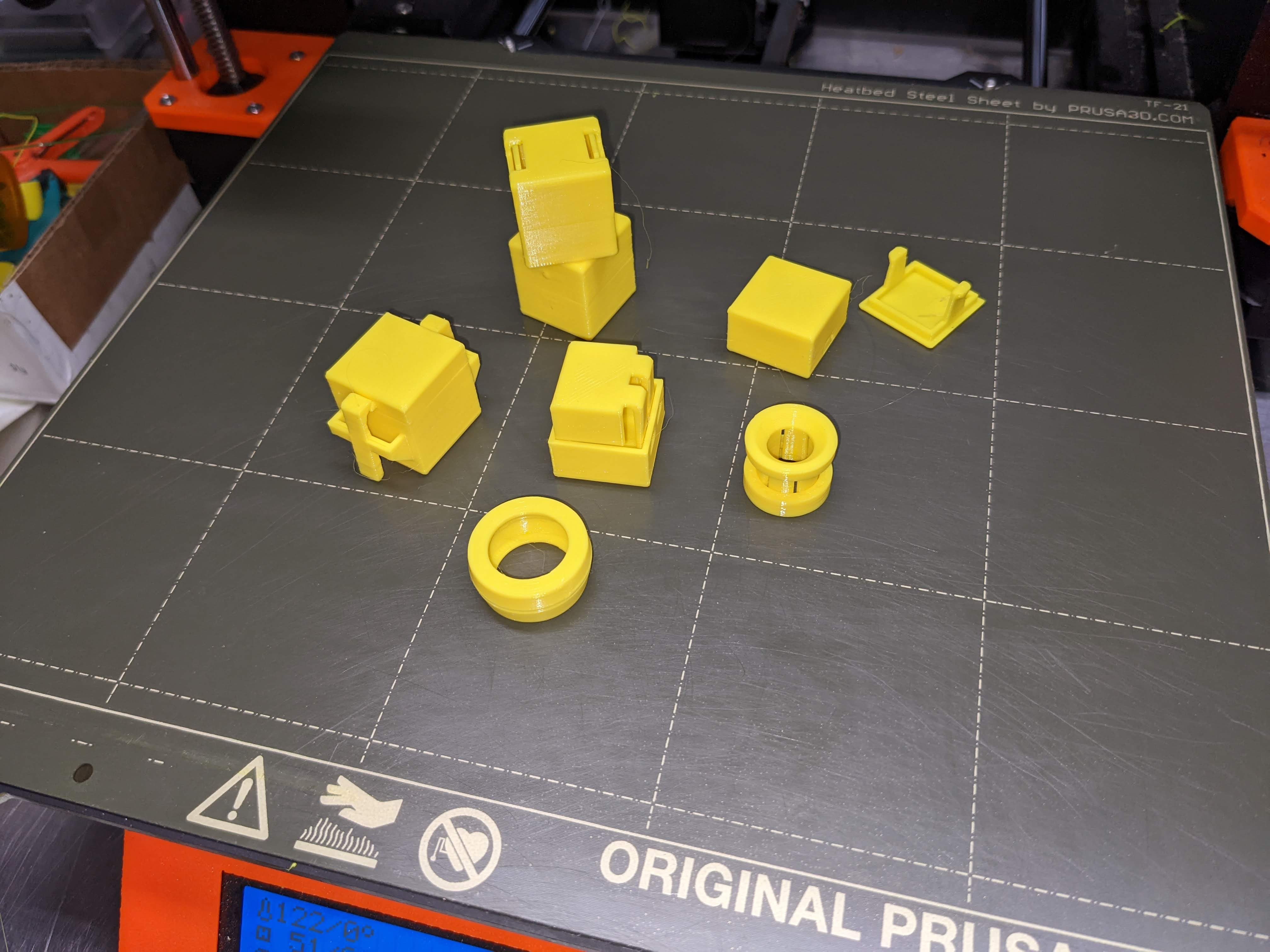
<p>This is a series of test prints which were inspired by the following MIT publication :</p><p><i><strong>Snap-Fit Joints for Plastics - A Design Guide</strong></i></p><p><a href="https://fab.cba.mit.edu/classes/S62.12/people/vernelle.noel/Plastic_Snap_fit_design.pdf">https://fab.cba.mit.edu/classes/S62.12/people/vernelle.noel/Plastic_Snap_fit_design.pdf</a></p><p>While the above paper is a discussion in the context of injected molded plastic parts, many of the considerations outlined in the paper also apply to 3D printed parts. In reading the paper, I determined that I have been designing snap-fit connections sub-optimally. In addition, some types of snap-fit connections were discussed which I have not used before.</p><p>I decided to make a series of test prints to try out some of the ideas in the paper to see how the different types of connections would work in practice. In doing so, I had to make some slight modifications to enable 3D printing of the parts. I also found some interesting differences in how the various types of connectors work, which I believe will be useful in designing future 3D prints. Note that I did not make versions of <i>all</i> of the different types of snap joints pictured in the publication, and no doubt there are many other possibilities than those pictured.</p><p>I strongly recommend reading the referenced publication to get the full benefit of these prints. It is especially useful to compare the illustrations in the publication to the actual 3D printed versions. To clarify the discussion below I will note that “cantilever” and “lug” refers to the flexible or hook part of a snap fit joint.</p><p>I created the following different types of snap-fit joints :</p><ol><li>Cantilever01 - the cantilever is tapered across the width of the cantilever (see <i>Figure 1</i> in the paper)</li><li>Cantilever02 - the cantilever is tapered across the thickness of the cantilever (see <i>Figure 1</i> in the paper)</li><li>CantileverRidgid - A combination of cantilever and rigid lugs (see <i>Figure 2</i> in the paper)</li><li>Separable - An easily separated snap-fit connection (see <i>Figure 3</i> in the paper). Open this version by squeezing the sides at the two “buttons”.</li><li>Separable02 - An easily separated snap-fit connection (see <i>Figure 3</i> in the paper). Open this version by pushing on the lugs through the openings in the bottom.</li><li>Annular - Segmented annular snap joint (see <i>Figure 4</i> in the paper).</li><li>AnnularContinuous - A deceptively simple snap joint with some subtle characteristics (see <i>Figure 6</i> in the paper). If you look at the two pieces before joining them together, the joint geometry is almost invisible. But if you carefully press the two pieces together all around the circumference they will be joined quite strongly (but can be separated again by prying apart with a knife blade).</li><li>Torsion - This is the most complicated version, and requires some trial and error to get torsion bar dimensions that will work (and these probably vary depending on the type of filament used) (see <i>Figure 5</i> in the paper). <strong>NOTE :</strong> Be sure to allow the print to cool thoroughly after printing or the torsion bar will develop a permanent twist and will not “spring” correctly.</li></ol><p><strong>Some additional observations on the torsion snap fit in particular :</strong></p><p>While I cannot claim to have made a thorough investigation of this fitting, I did notice a few things while making changes to get a working version that may be of use to others. For example :</p><ul><li>A rectangular profile torsion bar seems to work better than a circular profile.</li><li>A relatively long torsion bar seems to be useful to enable the bar to twist without permanent deformation.</li><li>The torque of the torsion bar is adjusted by changing the dimensions of the rectangular profile, so it is advised to design to make this change as simple as possible.</li><li>The lever end of the torsion bar should be angled slightly away from the adjoining wall, to allow room for the lever to “swing”.</li><li>The lever needs to have a fairly thick “backbone” to keep it from snapping in half (ask me how I know!).</li></ul><p>Even with all of the above, I have to admit that my torsion bar design, while it works as a proof of concept, needs much improvement. </p><h4>Print Instructions</h4><p>Print in PLA using the gcode or 3mf files provided. In general :</p><ul><li>0% infill</li><li>perimeters = 2 (except perimeters = 3 for Annular)</li></ul><p>Note that Cantilever02 uses the same bottom piece as Cantilever01.</p><h4>CAD</h4><p>The OnShape 3D CAD files for this are here :</p><p><a href="https://cad.onshape.com/documents/914103c80c8c1667caa3efed/w/4dc6e8fa645753fa1385ac15/e/040dc95225d1099f7d60a315">https://cad.onshape.com/documents/914103c80c8c1667caa3efed/w/4dc6e8fa645753fa1385ac15/e/040dc95225d1099f7d60a315</a></p><p> </p><p> </p>
With this file you will be able to print Snap-Fit Joint Test Prints - Eight Versions with your 3D printer. Click on the button and save the file on your computer to work, edit or customize your design. You can also find more 3D designs for printers on Snap-Fit Joint Test Prints - Eight Versions.