Speed Boat 2 RC
thingiverse
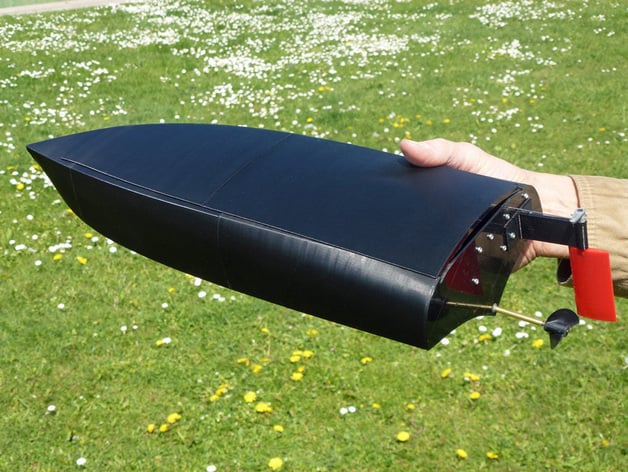
My first speedboat http://www.thingiverse.com/thing:312235\nwas built piece by piece from three different components. This time, it's a hull made from one continuous part with no need for splines or rails. Additional features include a deck to protect electronics. By sealing it with elastic tape and using a compensator grommet on the rudder steering rod, you can make it nearly unsinkable - although hopefully that won't be necessary. The overall length is 414mm. The camera mount http://www.thingiverse.com/thing:461044\nis also included for this design, allowing users to add a mini cam. Unlike previous versions, this one didn't require the assistance of my mermaid model; instead, I designed a flexible coupling in place of heat shrink tubes. Update:\nSmaller hull components with a height of 149mm have been uploaded.\nThe shortest possible height I could achieve is 127mm.\nUpdate July 7, 2015: \nI uploaded smaller deck parts with heights of 116mm and 117mm. Here are some video tutorials on YouTube for your reference: http://youtu.be/WKB13EdQD4Y http://youtu.be/e6QYdzF0Z5E
With this file you will be able to print Speed Boat 2 RC with your 3D printer. Click on the button and save the file on your computer to work, edit or customize your design. You can also find more 3D designs for printers on Speed Boat 2 RC.