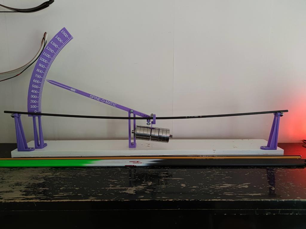
Spine-O-Matic - A spine tester for arrow shafts
thingiverse
I did all prints in PLA with 3 shells and 20% infill. No supports needed. A method to pause the print and change filament is needed if you want to change color for scale and lever markings. You need to print one piece of each part except for the arrowstand that you need to print 3 pieces of (it also doubles as a stand for the scale). Also if it isn't obvious you only need one of the scales. If you do not think you will ever need to test arrows with spines above 900 then print the scale that goes to 900 and save time and filament. 2021-09-19: Added a dummy bearing in case someone wants to build it without real ball bearings (you can always replace them with real bearings later). Apart from printed parts you also need the following: - 6 ball bearings with an inner diameter of 4mm and outer diameter of 13mm (I use U604ZZ) - 9 M4x12 screws (longer screws will also work) - 1 M4 screw long enough for some counterweight nuts and also attach end part to lever. - 1 M6 screw (short) for adjusting for different arrow shaft diameters. - some more M4 screws and some nuts to use as counterweights. - 4mm washers to put between ball bearings and plastic and also make the lever move easier. - an 880g weight (weight + centerpiece should weigh 880g). - some kind of board to mount everything to. Assembly instructions - Screw 4 of the ball bearings to two of the arrows stands. Use M4x12 screws and washers (optional but recommended9 - Mount the two arrows stands so that there is exactly 28 inch distance between the inner contact point between the ball bearing and the arrow shaft. - Assemble the lever and use an M4x12 screw and washers (on both sides) to the leverstand. It should be obvious from the pictures and the size of the hole where the M6 bolt should go. - Put a arrow shaft on the arrow stands and mount the lever so that the end part ends up at equal distance from earch arrow stand. Make sure the lever is parallell to the arrow shaft. - Use 2 M4x12 screws to attach the scale to the last arrow stand. - Mount the scale so that the end of the lever almost touches it but it should touch it. It is designed for having exactly 2 mm free space between the tip of the lever and the scale. - Attach the last two bearings to the centerpiece. The centerpiece is optional, if you use some other way to hang the weight on the shaft, like for example a string, you can skip it but having ball bearings on the weight will make it easier to spin the arrow. I recommended putting counterweights on the short part of the lever to make sure it has minimal impact on the result. The left part should be heavier (for obvious reasons) but not by much.
With this file you will be able to print Spine-O-Matic - A spine tester for arrow shafts with your 3D printer. Click on the button and save the file on your computer to work, edit or customize your design. You can also find more 3D designs for printers on Spine-O-Matic - A spine tester for arrow shafts.