Staggered Target (Nerf target practice)
thingiverse
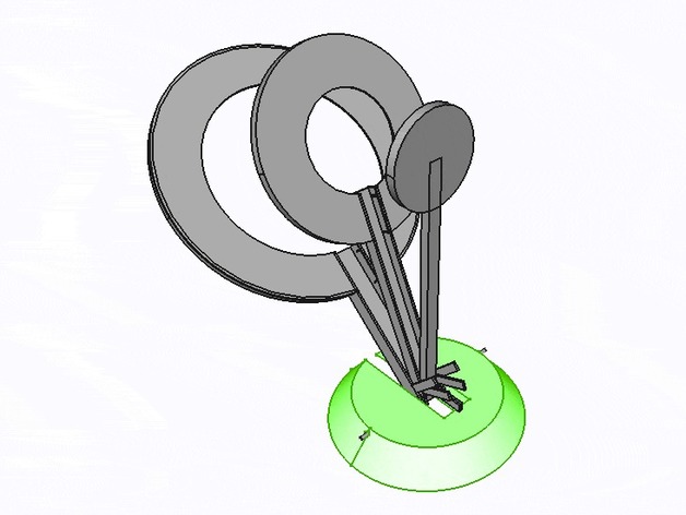
A simple three-tiered shooting target for Nerf. An easy guide to get started with FreeCAD design and 3D printing. About the target: Shoot the centre of the target to knock down all three rings. Shoot the middle target ring to knock down the outer two rings. Shoot the outer target ring to knock down only the outer ring. How I Designed This Getting started with FreeCAD – Objects A great feature of FreeCAD is working with solid 3D parts. Use the 'Part' Workbench. ('Workbench' is essentially a set of tools to show in the toolbar area) Part Workbench selection Create a 3D cylinder object and place it in 3D space. The example below is a small coin-like cylinder. Copy and paste the same cylinder or create a new one at the same placement. Then change the radius to be smaller by the amount we want the target rim edges to be. In our example, it's a tiny 0.2mm so the radius (half diameter) is 1.8mm. Then we position this cylinder back by 0.2mm ready to cut away leaving the sides and face. Select the larger of the two cylinders first then shift select the smaller cylinder we want to remove from the larger one. From the Part menu, select 'Boolean' > 'Cut' This should provide a cut-out cap-like object. If you look inside the 'Cut' Object in the 'Model' panel, you will notice the original objects (cylinders) are simply children of this new cut object. You can adjust the smaller cylinders placement and see the results. (Just remember when editing children that visual results do not show up instantly and you have to press enter or change input focus to trigger a render.) Have a play. Using these cut techniques, you can generate the full face of each target piece. Notice that by making a larger face and removing the center by 'cutting' a cylinder from our original 'Cut' object we end up with a more complex shape. You can 'Cut' Cuts, intersects, unions, and fusions over and over where you need to. Shown below, we use 'Union' to combine the smaller and larger faces of a target piece. We can then use a simple Cube object to create a cut in the face for the pivot (holder) for this target face. The resulting cut will allow us to build an arm to hold up the face and pivot from the base. You can use the techniques as described in previous steps just using Cubes instead of cylinders to create the arm your own way. Once you have your arm built, you should be feeling confident in using the boolean techniques to build up simple objects. We will want to add the little feet that prop up the face when used on a pivot. They are just little rectangles sticking out from the arm near the base, but allowing some height above the base for rotation (We don't build the base in this tutorial - but you can see it's a simple cone with a hinge/toothpick cylinder hole). Your little foot added to the arm should do the trick. However, maybe you want the target to be harder to knock down or you find the balance not quite right. We may need to adjust the angle of the feet. The angles in FreeCAD are set per object and by axis. Simply put, 90 degrees on the correct axis would be like moving a clock hand from 12 to 3. For a simple calculation like this, we would need to assign the axis to only 'x' (as example) so the axis might read X:1, Y:0, Z:0. You can play with the axis and see what you get. If rotations get hard to visualise, you can use a simple trick to do one axis at a time and copy/paste the object then use 'Union' to create a new object which has a fresh 0 degrees starting point then apply your next axis rotation. (It's not very efficient but fine for small projects). Once your foot is placed and angled to your satisfaction, you can create a mirror. A mirrored object just mirrors along a chosen axis/plane. We want our foot below to be one on both sides of the arm. We use the Mirroring option from the part menu. In our example, we want to mirror along the YZ plane. The result is a quick duplication of the foot on the other side of our model. The other parts are easily created using the techniques above. Have a play around and you will be able to change and improve upon this design :)
With this file you will be able to print Staggered Target (Nerf target practice) with your 3D printer. Click on the button and save the file on your computer to work, edit or customize your design. You can also find more 3D designs for printers on Staggered Target (Nerf target practice).