Star Trek Next Generation mini desktop monitor
prusaprinters
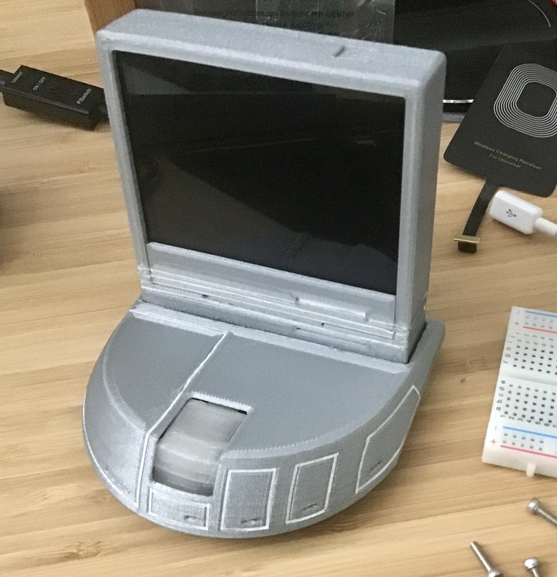
<p>Last Update 2022.02.06</p><p>THIS PROJECT IS STILL VERY MUCH A WORK IN PROGRESS - Bottom section needs a notch for 1 m2.5 screw to attach base lower panel to base upper panel. 2 versions of the base bottom panel are provided, if you don't need the extra space for a usb speaker board. You will need to have a good amount of raspberry pi familiarity to get this running the way it is shown in the demo.</p><figure class="media"><oembed url="https://youtu.be/VpyOh2fm7kE"></oembed></figure><p>As if the pimoroni hyperpixel 4.0" square screen wasn't enough in demand. This is a rough desktop monitor model based on the one shown in Star Trek: The Next Generation. This is a much smaller model than whatever they built for the show. I have wanted to build a shell for my heavily modified MagicMirror pi zero.</p><p>Total components used:</p><ul><li><a href="https://shop.pimoroni.com/products/hyperpixel-4-square?variant=30138251444307">Hyperpixel 4.0" square</a></li><li>Raspberry pi Zero / pi Zero 2</li><li><a href="https://www.adafruit.com/product/2419">TeensyLC</a></li><li><a href="https://www.microcenter.com/product/481583/manhattan-hi-speed-usb-20-4-port-micro-hub">USB Hub</a></li><li><a href="https://www.adafruit.com/product/1119">12mm x 6mm Button</a></li><li><a href="https://smile.amazon.com/gp/product/B071NR19BQ">USB Cable for power</a></li><li><a href="https://www.adafruit.com/product/1758">Sequin LED</a> x2 (Optional)</li><li><a href="https://smile.amazon.com/gp/product/B088CSDZQM">USB Speaker</a> for its board, <a href="https://smile.amazon.com/gp/product/B08RMQP6YP">Molex Wires</a> and <a href="https://www.adafruit.com/product/4227">Tiny Speaker</a> (Optional)</li><li><a href="https://hobbytape.net/shop">Crepe Tape</a> [1/32"] or model paint for your print material (optional)</li></ul><p> </p><p>Magic Mirror does not install successfully using default methods for a pi zero. I followed the guide given here - <a href="https://www.linuxscrew.com/raspberry-pi-magic-mirror">https://www.linuxscrew.com/raspberry-pi-magic-mirror</a></p><p>I created the LCARS-ified graphics / theme myself. When I have my copy of the Magic Mirror project code finalized, I will post it to my github and link to that from here. No ETA.</p><p>Early list of instructions for the MagicMirror build are here:<br><a href="https://github.com/lambtor/PicardDesktopMonitor-MagicMirror">https://github.com/lambtor/PicardDesktopMonitor-MagicMirror</a></p><p>Square display does not work well with the LCARS style sheet I created, as I had designed it for a 4:3 screen aspect ratio. The Screen Frame tab part allows you to see the bottom of the screen when you need it, like command prompt, etc. You should be able to pull my .css file and my index.html from the github, but you'll also want to install the LCARS font. Swiss911 needs to be installed on the pi zero, so you'll need to be able to do this from a command prompt.</p><ul><li>Copy a new TrueType fonts (*.ttf) font file in the directory /usr/share/fonts (for all users)</li></ul><p>Main frame is 1 or 2 pieces, with cutouts for SD card and an optional camera tray. Camera Tray cutout should fit <a href="https://www.raspberrypi.org/products/camera-module-v2/">https://www.raspberrypi.org/products/camera-module-v2/</a> You will need an adapter ribbon cable to connect the camera to a pi zero w. I used a no-solder header kit for pi zero to connect to the hyperpixel.</p><p>hyperpixel : <a href="https://shop.pimoroni.com/products/hyperpixel-4-square?variant=30138251444307">https://shop.pimoroni.com/products/hyperpixel-4-square?variant=30138251444307</a></p><p>pi zero headers: <a href="https://shop.pimoroni.com/products/gpio-hammer-header?variant=35643241098">https://shop.pimoroni.com/products/gpio-hammer-header?variant=35643241098</a></p><p>usb 2.0 hub (you'll want to pop it out of its plastic shell): <a href="https://www.microcenter.com/product/481583/manhattan-hi-speed-usb-20-4-port-micro-hub">https://www.microcenter.com/product/481583/manhattan-hi-speed-usb-20-4-port-micro-hub</a></p><p>Base is 3 pieces - a top section, bottom panel, and a button. Button is planned to be wired to a <a href="https://www.adafruit.com/product/2419">TeensyLC</a> to trigger display on/off by hitting the keyboard "pause" key, and should be printed in TPU. </p><p>The .ino script file provided is meant to allow you to program the TeensyLC so the main button will send keyboard presses to the pi. The main button prongs should be wired to teensy pin 23 and GND, so the following happens:</p><p>button pressed for < 2 seconds = display off / display on</p><p>button pressed for < 5 seconds = full reload of magic mirror page</p><p>button pressed for > 5 seconds = full shutdown of pi</p><p>The lights for the main button are LED sequins in white from adafruit:</p><p><a href="https://www.adafruit.com/product/1758">https://www.adafruit.com/product/1758</a></p><p>Inner button shelf is sized to fit a 12mm x 6mm </p><p><a href="https://www.adafruit.com/product/1119">https://www.adafruit.com/product/1119</a> </p><p>The button is meant to trigger the mapped TeensyLC pin. Base has 2 cutouts for usb cables. I used these: <a href="https://smile.amazon.com/gp/product/B071NR19BQ">https://smile.amazon.com/gp/product/B071NR19BQ</a></p><p>Sounds are done by SEVERELY hacking a usb speaker I got here:</p><p><a href="https://smile.amazon.com/gp/product/B088CSDZQM">https://smile.amazon.com/gp/product/B088CSDZQM</a></p><p>I ripped the electronics board out of this enclosure, and made a custom molex cable for it. The sound board is the black square-ish part on the right side of the internal guts photo. Wires to plug into the board for USB and speaker used this kit:</p><p><a href="https://smile.amazon.com/gp/product/B08RMQP6YP">https://smile.amazon.com/gp/product/B08RMQP6YP</a></p><p>Actual speaker is also from adafruit:</p><p><a href="https://www.adafruit.com/product/4227">https://www.adafruit.com/product/4227</a></p><p>I cut the wires to the size I wanted, soldered them to one of the usb hub's ports.</p><p>The model needs to be simplified a bit, as originally there was a plan for a separate physical button to trigger safe shutdown. I've included it in the STL files, but you're best off not printing that, and also better off removing the “U” section in the baseTop by cutting it from the model or snipping it off with offset shears.</p><p>The prong that extends in from the inner ceiling of the display frame should snap onto a screw used to attach the pi zero to the hyperpixel back. Use m2.5 x 8mm nuts & m2.5 screws on the lower 2 pi zero screw holes so the board tries to sit evenly against the back of the hyperpixel.</p><p>The notches on all parts can be filled in with paint, if you're skilled at that, or you can use white duct tape cut to really thin strips. The tape cut STL was created to make this easier, as you should be able to run an exacto knife around the roll with that as a guide.</p>
With this file you will be able to print Star Trek Next Generation mini desktop monitor with your 3D printer. Click on the button and save the file on your computer to work, edit or customize your design. You can also find more 3D designs for printers on Star Trek Next Generation mini desktop monitor.