G0602 Lathe Encoder Mount
thingiverse
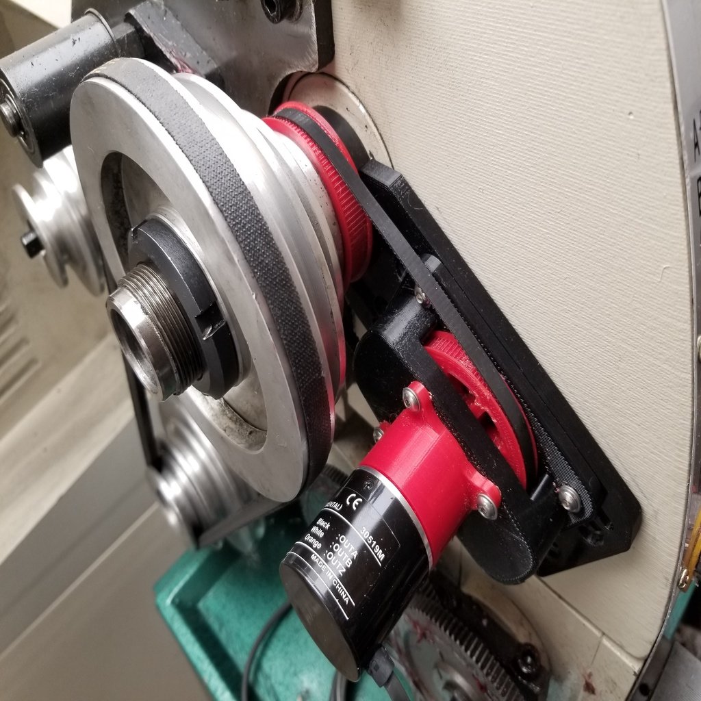
This project is an encoder mount for Clough42’s Electronic Leadscrew for the Grizzly G0602 lathe. James has done an excellent job in his YouTube video series which can be found here: https://www.youtube.com/playlist?list=PLDlWKv7KIIr90ZZ7Zqt-ge5nVVdS3WVgg This collection includes the printed parts to mount the encoder as well as a pair of 3GT pulleys: one for the spindle and a second pulley that drives the encoder using a 162 tooth 3GT 6mm belt. The design offers belt adjustability, an encoder pulley that rides on two 10x26x8 bearings and utilizes an encoder coupler to decouple the pulley load from the encoder. This all fits within the G0602 lathe’s pulley cover. This encoder mount can be used to mount the encoder, but is only a small part to completing the electronic lead screw as described in the above YouTube series. Models included in this collection: Alignment tool Base Housing Mount Slider 3GT Encoder Pulley 3GT Spindle Pulley Viewing Gallery Photos: If the photo appears as a gear in the gallery, click the expand icon in the upper right of the photo, and click the 'View Original' link. Required Fasteners: (4) M6 x 1 x 16 (4) Button Head Cap Screws (base mounting to lathe) (4) M6 Flat Washers (base mounting to lathe) (8) M4 x 0.7 x 16 Button Head Cap Screws (slider plate to base, slider to housing) (12) M4 Flat Washers (slider plate to base – 2 per screw, encoder mount to slider) (4) M4 Square Nuts (slider to base) (4) M4 x 0.7 x 12 Button Head Cap Screws (encoder mount to slider) (3) M3 x 0.5 x 10 Button Head Cap Screws (encoder to encoder mount) (3) M3 Flat Washers (encoder to encoder mount) Additional Parts: (2) 10 x 26 x 8 Bearings (6000-2RSH SKF or equivalent) (1) 3GT Belt 396mm 132 teeth 6mm (Mitsumi GBN3963GT-60 or equivalent) Tools: Electric Hand Drill Level Sharpie 6mm x 1.0 tap 5mm drill bit (or #8 or 13/64" drill for 6M tap) 4mm x 0.7 tap Tap Handle 1.5mm, 2.0mm, 2.5mm, and 4mm Allen Wrenches Mounting Instructions: The encoder mount requires the removal of the lathe spindle belt and pulley and lead screw gears as well as drilling and tapping holes for M6 screws. 1. Open the pulley cover on the G0602 lathe. 2. Remove the lead screw gears and gear support stud. 3. Remove the spindle lock nuts. 4. Remove the belt and aluminum spindle pulley. 5. Remove the plastic lead screw spindle gear. 6. Mount the base plate to the lathe. a. Position the curved section of the base against the spindle spacer (the spacer sits behind the spindle gear that was removed previously). b. Set the alignment tool on top of the base. c. Use a level to level the alignment tool. When level, the alignment tool positions the base at a 30-degree angle. Exactly 30 degrees isn’t important so if the alignment tool is horizontal with the level, it will be close enough. d. Mark the top of the base with a sharpie and mark the holes for drilling. e. Use a 5mm drill bit (or #9 or 13/64” drill) to drill the 4 mounting holes in the side of the lathe. f. Use an M6 x 1.0 tap to tap the holes. 7. Assemble the mount a. Press a bearing into the 3D printed slider. b. Use the M4 x 0.7 tap to chase the 8 threaded holes in the housing. c. Press the 2nd bearing into the 3D printed housing. It should be flush with the inner u-shaped side. d. Place the belt over the 3D printed encoder pulley and insert the pulley into the housing. Note the belt should straddle the housing standoff marked with the arrow and the pulley side with the stepped shaft should go into the housing. The 6mm stepped shaft is where the encoder coupling will mount. e. Insert the other side of the pulley into the slider. f. Use 4 M4 x 16 button head cap screws to mount the slider to the housing. g. Use 4 M4 x 16 button head cap screws, 8 M4 washers and 4 M4 square nuts to mount the slider to the base. Note: the housing arrow and belt should be positioned toward the curved part of the base. Move the slider in the slots so it is closest to the curved side of the base and loosely tighten the screws (these will be adjusted later). 8. Install the encoder a. Mount the encoder to the encoder mount using the 3 M3 x 10 button head cap screws. Note: Position the encode mount so the port sits on the housing side that is opposite of the belt. b. Slide the encoder coupler onto the encoder shaft and use a 1.5mm Allen wrench to tighten the coupler onto the encoder shaft. c. Mount the encoder mount onto the housing with the 4 M4 X 12 button head cap screws. As you position the encoder mount, slide the coupler over the 6mm step in the pulley. Note: position the ‘port’ on the encoder mount toward the housing standoff that is opposite the belt. d. Push the pulley towards the encoder, and use the 1.5mm Allen wrench to tighten the coupler. 9. Mount the Base onto the lathe a. Slide the belt over the spindle and onto the 3D printed spindle pulley. b. Fasten the base to the lathe using the M6 x 16 button head cap screws and tighten using the 4mm Allen wrench. c. Adjust the belt tension by sliding the slider outward and tightening the M4 screws on the slider. Note: do not over-tension the belt. It should be tight enough not to slip, but still flex inward when pushing on it with your finger. 10. Route the encoder cable appropriately. 11. Reinstall the lathe spindle pulley. 12. Adjust the spindle lock nuts for the recommended 0.001" - 0.005" axial bearing play. 13. Reinstall the spindle drive belt. REVISIONS: Housing_r03.stl -- increased housing stand off to 13.5mm (from 12mm). Housing_r04.stl -- added arrow and port text to housing. Updated instructions.
With this file you will be able to print G0602 Lathe Encoder Mount with your 3D printer. Click on the button and save the file on your computer to work, edit or customize your design. You can also find more 3D designs for printers on G0602 Lathe Encoder Mount.