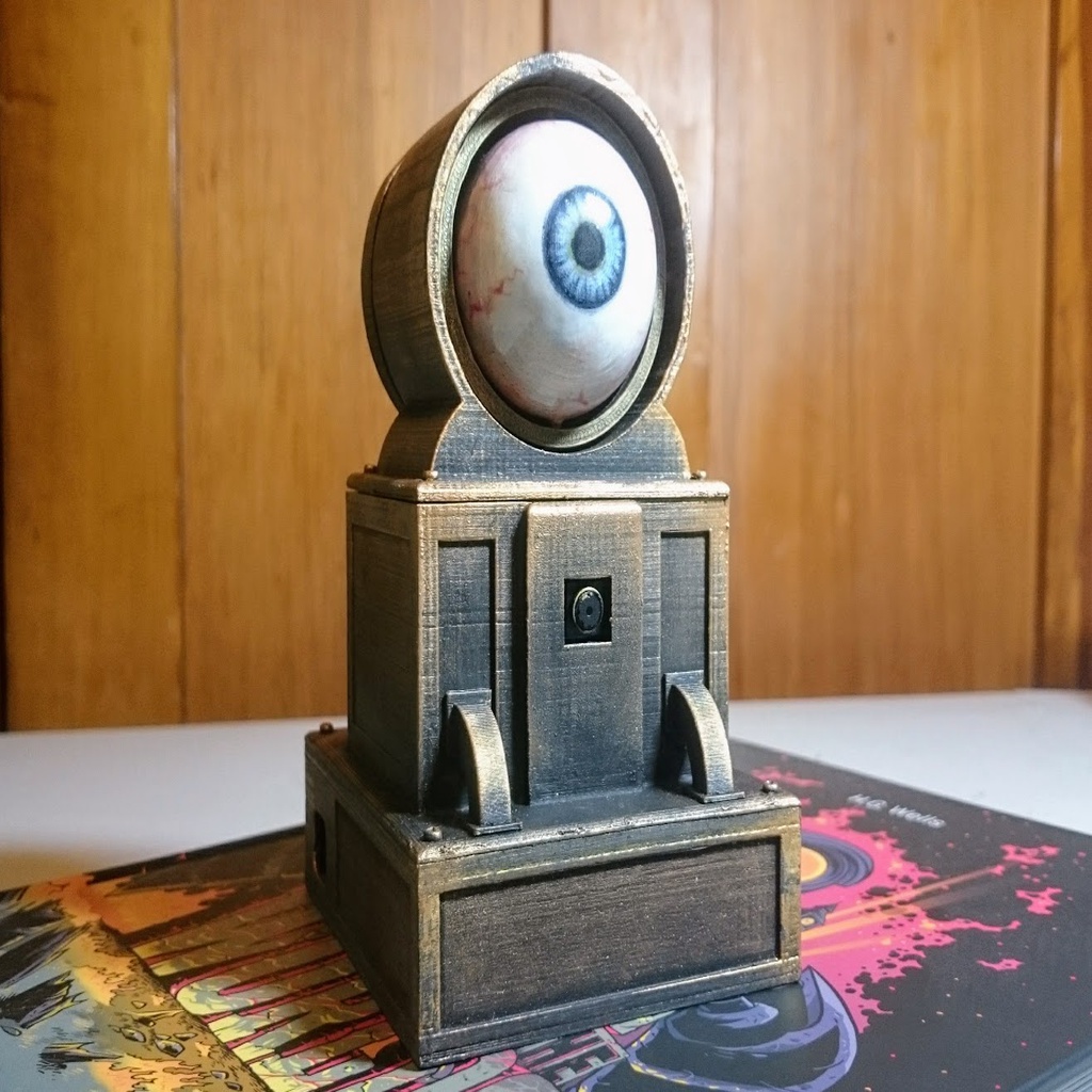
Steampunk Oculus Roboticus
thingiverse
A robotic eyeball powered by Raspberry PI + Camera, 2 servos and OpenCV.\r\n\r\n* [Raspberry Pi](https://aliexpress.com/item/32848719606.html)\r\n* [Micro Servos](https://www.aliexpress.com/item/32975618090.html) \r\n* [Pi Camera](https://www.aliexpress.com/item/33015445002.html)\r\n* [Screws](https://www.aliexpress.com/item/32598285502.html)\r\n* [Wire](https://www.aliexpress.com/item/32916840857.html)\r\n\r\nGet OpenCV up and running on the Pi with this guide, or upload an image somewhere if you get time. You'll also need pigpio.\r\n\r\n1. Print lower level\r\n2. Use small screws from the micro servo to fit the Raspberry Pi.\r\n3. Print middle level\r\n4. Cut 4 screws to length and screw the camera in to the middle level.\r\n5. Print servo bracket\r\n6. Screw in the servos - see pic\r\n7. Glue servo mount to base of top level, over locator marks.\r\n8. Print two levers and their axle\r\n9 Slide levers onto axle and locate axle into axle bracket in top level. Fix it with a tiny blob of glue.\r\n10. Print top level back plate and pipes. You may need to angle big pipe and print with raft and supports.\r\n11. Glue big pipe to back of back plate, then small pipe to big pipe.\r\n12. Print and paint eyeball and middle ring.\r\n13. Loosely assemble and paint top, middle and bottom levels, along with back plate and pipes.\r\n14. Disassemble\r\n15. Clip eyeball into middle ring by applying pressure at sides.\r\n16. Do similar to attach middle ring to top level housing.\r\n17. Cut a length of wire for pull rod to attach from top link in the back of the eye to the tall lever.\r\n18. Repeat to create a rod from right link in the back of the eye to the shorter lever.\r\n19. Make two more rods to attach to perpendicular sides of levers to servos.\r\n20. Attach all cables to Pi.\r\n21. Tighten screws and power up.\r\n22. Unzip TheEye.zip onto Pi and run main.py to start the eye.\r\n\r\nFrom layershifter's comments:\r\nI could have hidden camera a bit more, but it already has quite a narrow field of view. I'd probably use a fisheye lens in retrospect, or multiple cameras. The pipes at the back were just an after thought to provide a distraction from the back plate a bit.\r\n\r\nPerhaps for version 2.0!\r\n* [Raspberry Pi](https://aliexpress.com/item/32848719606.html)\r\n* [Micro Servos](https://www.aliexpress.com/item/32975618090.html) \r\n* [Pi Camera](https://www.aliexpress.com/item/33015445002.html)\r\n* [Screws](https://www.aliexpress.com/item/32598285502.html)\r\n* [Wire](https://www.aliexpress.com/item/32916840857.html)\r\n\r\nFollow this guide or upload an image somewhere if you get time. You'll also need pigpio.\r\n\r\n1. Print lower level\r\n2. Use small screws from the micro servo to fit the Raspberry Pi.\r\n3. Print middle level\r\n4. Cut 4 screws to length and screw the camera in to the middle level.\r\n5. Print servo bracket\r\n6. Screw in the servos - see pic\r\n7. Glue servo mount to base of top level, over locator marks.\r\n8. Print two levers and their axle\r\n9 Slide levers onto axle and locate axle into axle bracket in top level. Fix it with a tiny blob of glue.\r\n10. Print top level back plate and pipes. You may need to angle big pipe and print with raft and supports.\r\n11. Glue big pipe to back of back plate, then small pipe to big pipe.\r\n12. Print and paint eyeball and middle ring.\r\n13. Loosely assemble and paint top, middle and bottom levels, along with back plate and pipes.\r\n14. Disassemble\r\n15. Clip eyeball into middle ring by applying pressure at sides.\r\n16. Do similar to attach middle ring to top level housing.\r\n17. Cut a length of wire for pull rod to attach from top link in the back of the eye to the tall lever.\r\n18. Repeat to create a rod from right link in the back of the eye to the shorter lever.\r\n19. Make two more rods to attach to perpendicular sides of levers to servos.\r\n20. Attach all cables to Pi.\r\n21. Tighten screws and power up.\r\n22. Unzip TheEye.zip onto Pi and run main.py to start the eye.\r\n\r\nFrom layershifter's comments:\r\nI could have hidden camera a bit more, but it already has quite a narrow field of view. I'd probably use a fisheye lens in retrospect, or multiple cameras. The pipes at the back were just an after thought to provide a distraction from the back plate a bit.\r\n\r\nPerhaps for version 2.0!\r\n* [Raspberry Pi](https://aliexpress.com/item/32848719606.html)\r\n* [Micro Servos](https://www.aliexpress.com/item/32975618090.html) \r\n* [Pi Camera](https://www.aliexpress.com/item/33015445002.html)\r\n* [Screws](https://www.aliexpress.com/item/32598285502.html)\r\n* [Wire](https://www.aliexpress.com/item/32916840857.html)\r\n\r\nFollow this guide or upload an image somewhere if you get time. You'll also need pigpio.\r\n\r\n1. Print lower level\r\n2. Use small screws from the micro servo to fit the Raspberry Pi.\r\n3. Print middle level\r\n4. Cut 4 screws to length and screw the camera in to the middle level.\r\n5. Print servo bracket\r\n6. Screw in the servos - see pic\r\n7. Glue servo mount to base of top level, over locator marks.\r\n8. Print two levers and their axle\r\n9 Slide levers onto axle and locate axle into axle bracket in top level. Fix it with a tiny blob of glue.\r\n10. Print top level back plate and pipes. You may need to angle big pipe and print with raft and supports.\r\n11. Glue big pipe to back of back plate, then small pipe to big pipe.\r\n12. Print and paint eyeball and middle ring.\r\n13. Loosely assemble and paint top, middle and bottom levels, along with back plate and pipes.\r\n14. Disassemble\r\n15. Clip eyeball into middle ring by applying pressure at sides.\r\n16. Do similar to attach middle ring to top level housing.\r\n17. Cut a length of wire for pull rod to attach from top link in the back of the eye to the tall lever.\r\n18. Repeat to create a rod from right link in the back of the eye to the shorter lever.\r\n19. Make two more rods to attach to perpendicular sides of levers to servos.\r\n20. Attach all cables to Pi.\r\n21. Tighten screws and power up.\r\n22. Unzip TheEye.zip onto Pi and run main.py to start the eye.\r\n\r\nFrom layershifter's comments:\r\nI could have hidden camera a bit more, but it already has quite a narrow field of view. I'd probably use a fisheye lens in retrospect, or multiple cameras. The pipes at the back were just an after thought to provide a distraction from the back plate a bit.\r\n\r\nPerhaps for version 2.0!\r\n* [Raspberry Pi](https://aliexpress.com/item/32848719606.html)\r\n* [Micro Servos](https://www.aliexpress.com/item/32975618090.html) \r\n* [Pi Camera](https://www.aliexpress.com/item/33015445002.html)\r\n* [Screws](https://www.aliexpress.com/item/32598285502.html)\r\n* [Wire](https://www.aliexpress.com/item/32916840857.html)\r\n\r\nFollow this guide or upload an image somewhere if you get time. You'll also need pigpio.\r\n\r\n1. Print lower level\r\n2. Use small screws from the micro servo to fit the Raspberry Pi.\r\n3. Print middle level\r\n4. Cut 4 screws to length and screw the camera in to the middle level.\r\n5. Print servo bracket\r\n6. Screw in the servos - see pic\r\n7. Glue servo mount to base of top level, over locator marks.\r\n8. Print two levers and their axle\r\n9 Slide levers onto axle and locate axle into axle bracket in top level. Fix it with a tiny blob of glue.\r\n10. Print top level back plate and pipes. You may need to angle big pipe and print with raft and supports.\r\n11. Glue big pipe to back of back plate, then small pipe to big pipe.\r\n12. Print and paint eyeball and middle ring.\r\n13. Loosely assemble and paint top, middle and bottom levels, along with back plate and pipes.\r\n14. Disassemble\r\n15. Clip eyeball into middle ring by applying pressure at sides.\r\n16. Do similar to attach middle ring to top level housing.\r\n17. Cut a length of wire for pull rod to attach from top link in the back of the eye to the tall lever.\r\n18. Repeat to create a rod from right link in the back of the eye to the shorter lever.\r\n19. Make two more rods to attach to perpendicular sides of levers to servos.\r\n20. Attach all cables to Pi.\r\n21. Tighten screws and power up.\r\n22. Unzip TheEye.zip onto Pi and run main.py to start the eye.\r\n\r\nFrom layershifter's comments:\r\nI could have hidden camera a bit more, but it already has quite a narrow field of view. I'd probably use a fisheye lens in retrospect, or multiple cameras. The pipes at the back were just an after thought to provide a distraction from the back plate a bit.\r\n\r\nPerhaps for version 2.0!
With this file you will be able to print Steampunk Oculus Roboticus with your 3D printer. Click on the button and save the file on your computer to work, edit or customize your design. You can also find more 3D designs for printers on Steampunk Oculus Roboticus.