Stimpak (Fallout 4)
thingiverse
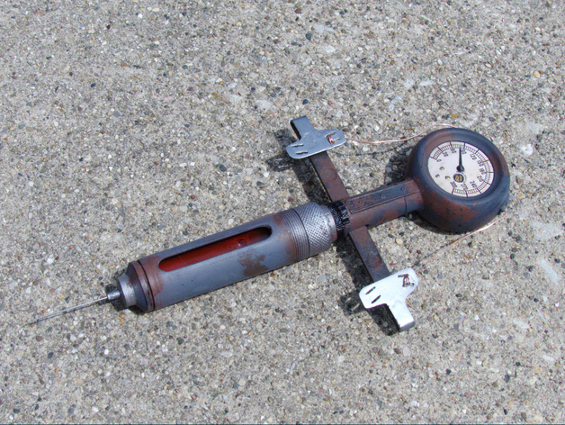
This text appears to be a detailed guide for creating a miniature replica of a medical device from the Fallout universe, specifically a Stimpack gauge. The author provides a step-by-step instructions on how to build this intricate model using various materials and tools. Here are some key points highlighted from the text: 1. **Materials needed**: Epoxy resin, copper wire, glass test tube, Tamiya masking tape, diamond bead reamer, candle flame, cold water, Noodler's calligraphy ink, rubber stopper, X-Acto knife, quilting pin, Mod Podge, spray adhesive. 2. **Printing the gauge**: The author used an Ultimaker 2 with 0.12mm layers and did not use supports, which resulted in a fragile print. They recommend using supports for better results. 3. **Gauge assembly**: The steps include attaching the arms, epoxying the tabs, adding wires, inserting the test tube, attaching the endcap, and final assembly. 4. **Test tube preparation**: The author cut down a glass test tube to fit into the barrel, filled it with red calligraphy ink, and secured it with epoxy and a rubber stopper. 5. **Needle preparation**: A long quilting pin was used as the needle, which butts up against the rounded end of the test tube, making it secure without any adhesive. 6. **Final assembly**: The barrel was screwed into the gauge, and the needle was pushed through the hole in the endcap. 7. **Printing notes**: The author provides tips on printing the gauge and the gauge needle, including using supports, small layers, and a smaller nozzle for better results. 8. **Tips for bending parts**: They advise printing the tabs on the ends of the arms in their upright position to ensure they bend rather than snap when flexed.
With this file you will be able to print Stimpak (Fallout 4) with your 3D printer. Click on the button and save the file on your computer to work, edit or customize your design. You can also find more 3D designs for printers on Stimpak (Fallout 4).