Strength Test Facility for Open Source Appropriate Technology (OSAT) 3D Printing
thingiverse
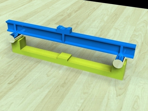
A Test Bed and sample Test Pieces for strength / stiffness testing of 3D Printed parts (See attached Word document for a detailed description) I am recording my development process and experiments in more detail on my blog: http://julianh72.blogspot.com/ I will continue to post relevant files here on Thingiverse, but I will have more space for discussion and debate on my blog. The first entry is here: http://julianh72.blogspot.com/2011/11/testing-strength-of-reprap-printed.html but there will be more discussion on later posts. EDIT 02 December 2011 - Modified parts (Mk II) uploaded, to make the test assembly more stable. The strength and stiffness of components manufactured using RepRap and other 3D Printing technologies are affected by a number of independent and inter-dependent parameters, including: a) the generic stock material used (e.g. PLA, ABS, PE, etc) b) the actual source and condition of the stock material; e.g. it has been reported that PLA filament will absorb atmospheric humidity over time, and this affects its condition when placed using RepRap-type fabrication; it has also been reported that different coloured batches of otherwise nominally identical filament from the same source can exhibit significantly different fabrication properties, and therefore presumably different mechanical properties c) the tool-path and build parameters which are used to fabricate the component (e.g. filament diameter, layer thickness, number of layers in the surface “shellâ€, % solid fill vs. % voids used in the core fill, etc) d) the orientation of the part during printing (filaments parallel or perpendicular to the main load paths, etc) e) the attributes of the actual printer (print head speed, precision / repeatability of placing the print head, backlash, etc) When manufacturing components which are intended to have mechanical strength and function, it is necessary to be able to measure the actual strength of materials which can be printed with a particular machine, using a particular set of printing parameters, so that the strength and service life of the component can be predicted, and to assist in the design of new components which will be subjected to loads whose magnitude can be predicted or estimated. This project came about partly because I am an engineer, and I “need to know†these sorts of things, but was also spurred on by reading an paper on “3-D Printing of Open Source Appropriate Technologies for Self-Directed Sustainable Development†by Pearce, Blair, Laciak, Andrews, Nosrat & Zelenika-Zovko. [Ref: www.ccsenet.org/jsd “Journal of Sustainable Development†Vol. 3, No. 4; December 2010 http://www.ccsenet.org/journal/index.php/jsd/article/view/6984/6385 ] Instructions ï® Print one (or more) Test Beds. ï® Print sufficient identical Test Pieces for the testing program. Keep records of the build and print parameters used (material, used, machine settings, % solid core fill, etc). Weigh the test pieces as a record of overall effective density. Where scales of only limited precision are available, weigh five or more identical pieces in a single weighing to get an effective mean sample weight. ï® It is suggested that a minimum of three identical test pieces should typically be printed whenever undertaking a formal testing and reporting program, although a single test piece can still yield useful insights into material behaviour when trying to determine a “semi-quantitative†assessment of comparative properties yielded by different printer settings etc. If the set of Test Pieces are printed as a nested suite in a single print run (rather than as a series of sequential print runs), this will ensure all pieces are manufactured under identical conditions, minimising variations due to machine preparation, operator skill, environmental conditions (temperature , humidity, dust), etc. It should be possible to arrange a suite of 5 or even 10 identical test pieces to be produced in a single print run in this way. ï® Consider printing sets of test pieces in different orientations when it is desired to understand the 3-dimensional orthotropic characteristics of the material. ï® Install steel pins on test bed, and place test piece on pins ï® Measure the clearance between the underside of the Test Piece and the Deflection Measuring Pad on the Test Bed ï® Apply an initial load increment (well below the anticipated failure load) and measure the mid-span deflection ï® Apply additional load increments and measure the deflection at each increment. It is recommended that data points should be entered into a graphing Spreadsheet or similar as it is recorded, to allow trends to be identified immediately (e.g. possible deflection reading errors, non-linear behaviour may indicate onset of failure, etc) ï® Repeat for each test piece in a suite, so that statistically meaningful results can be obtained. ï® Repeat for different manufacturing orientations, so that the influence of orthotropic material properties can be assessed.
With this file you will be able to print Strength Test Facility for Open Source Appropriate Technology (OSAT) 3D Printing with your 3D printer. Click on the button and save the file on your computer to work, edit or customize your design. You can also find more 3D designs for printers on Strength Test Facility for Open Source Appropriate Technology (OSAT) 3D Printing.