Stylish Lights for the Prusa I3 Bear Upgrade Frame
prusaprinters
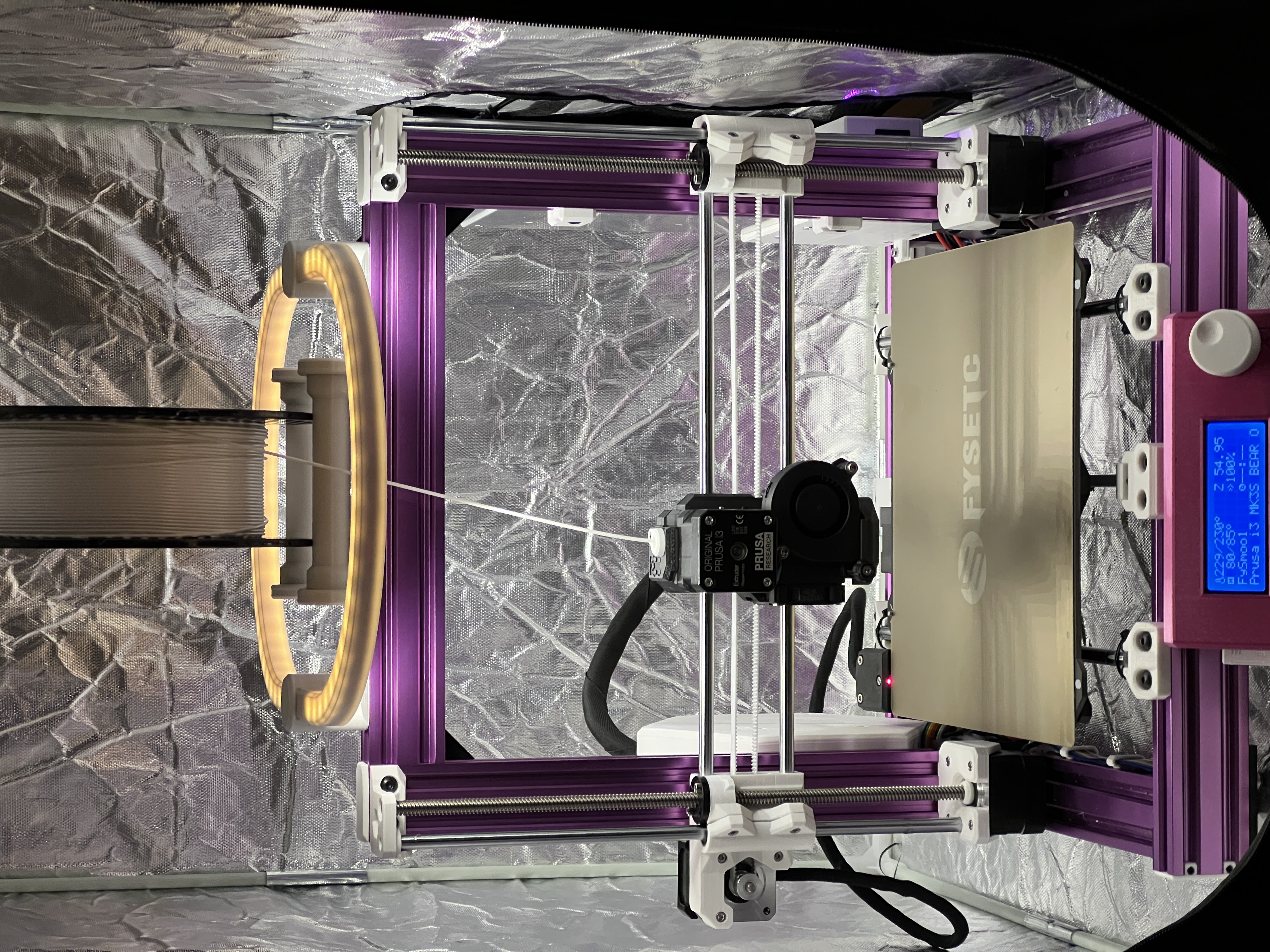
<p>Behold! Stylish lights for your Prusa I3 with the Bear Upgrade frame! Supply the LED strip and power supply of your own choosing, and with a bit of soldering, you've got gorgeous light to illuminate your print bed.</p><p><strong>Step 1: Things You'll Need</strong></p><p>In addition to the printed parts, you'll need to select an LED strip. It should be the type that can be cut to length and has pads on which to solder leads. In addition, you'll need some way to power the LED strip. Many come with their own power supply, and some even have dimming capabilities -- it's up to you. The LED strip should be 10mm wide at the absolute maximum. I purchased an 8mm strip and it fit perfectly. I used this LED strip, which has a very nice color temperature, and comes with an AC adaptor and a nice dimmer:</p><p><a href="https://amzn.to/3fP9pFU?tag=tv-auto-20">https://amzn.to/3fP9pFU</a></p><p>Needless to say, you'll also need to have some soldering experience. We'll just be soldering wires onto copper pads, so it's nothing tricky, I promise. I used a couple short pieces of this wire -- it's very flexible, easy to solder, and heat resistant:</p><p><a href="https://amzn.to/31knS93">https://amzn.to/31knS93</a></p><p>You'll also need two M5x8mm socket head cap screws.</p><p>Have this stuff ready? Great! Let's build.</p><p><strong>Step 2: Printing the Parts</strong></p><p>You'll need to print two shells, two reflectors, two self-locking t-nuts, and one left and one right clip.</p><p>The reflectors should be white or a very light color. This is important because this fixture delivers indirect light, bouncing the LED light off a curved surface inside the reflector. The material chosen will have a strong effect on the color and quality of the light output.</p><p>The shell and clip colors are up to you. I chose Galaxy Black Pruament for my prints, and I think it has a classy, solid look, like machined metal. It goes well with the textured surface of the printer's frame, but there are many options.</p><p><strong>Step 3: Installing the LED Strips Into the Reflectors</strong></p><p>Cut two lengths of LED strip to fit the outside, flat wall of each reflector. You may need to cut the strip shorter in order to get an integral number of sections. Apply solder to the pads at both ends of each length to make later assembly easier.</p><p>To make it easier to get the LED strip lined up, I used this trick: I gently lifted the backing in the middle of each length, and folding up a little bit as a tab so I could peel it up easily later. I then started from the middle of the reflector, gradually pulling away the backing while pushing the LED strip into place.</p><p><strong>Step 4: Mating the Reflectors to the Shells</strong></p><p>Press the reflectors into the shells. The open sides should face the same direction. Push hard, the reflector should be about 1mm below the edge of the shell. Set the shell/reflectors aside.</p><h5>Step 5: Decisions</h5><p>First, take a look at both clips. Note that there is a hole on one side to run the power cord. You need to decide whether you want the lugs facing inward, which looks more compact, or on the outside to avoid colliding with wide reel holders, etc. You could even run the power cord out of the front if you need to.</p><p>Next, decide which side you want the wire to come out. Push the power wire into the bottom hole, and lead an inch or so out through either one of the openings.</p><p>On the opposite clip, lead four inches of black and red wires directly across the openings for the light rings. This will be the interconnection wire.</p><h5>Step 6: Attaching the Mounting Hardware</h5><p>In each clip, push an M5x8mm screw through the counterbored hole from the top. Twist on a self-locking t-nut with the larger side toward the part. Go just a couple of turns; this will self-lock with the aluminum extrusion during final assembly.</p><h5>Step 6: Attaching the Shells to the Clips</h5><p>Lay the parts out in the orientation they will be in when attached to the printer. Push the shell/reflector assemblies into place leading the wires into the reflector where necessary, An optional bit of cyanoacrylate adhesive will make the assembly permanent.</p><p><strong>Step 7: Soldering</strong></p><p>Solder the incoming power supply wires to the nearby pads on the LED strip. Watch that polarity! When done, apply power to make sure it lights properly.</p><p>One the other side, solder the interconnection wire between the ends of the LED strips, matching positive to positive, and negative to negative. Again, when finished, apply power to make sure the connection are correct.</p><p><strong>Step 8: Placement and Testing</strong></p><p>Place the assembly over the top of the printer frame, allowing the t-nuts to slide into the slots. Turn the screws clockwise to engage the nut, and continue turning to tighten. Do not over-tighten – just close the gap and go a bit further. Apply power and enjoy!</p>
With this file you will be able to print Stylish Lights for the Prusa I3 Bear Upgrade Frame with your 3D printer. Click on the button and save the file on your computer to work, edit or customize your design. You can also find more 3D designs for printers on Stylish Lights for the Prusa I3 Bear Upgrade Frame.