SuperPINDA Precision Adjuster for Prusa i3 MK3S+
prusaprinters
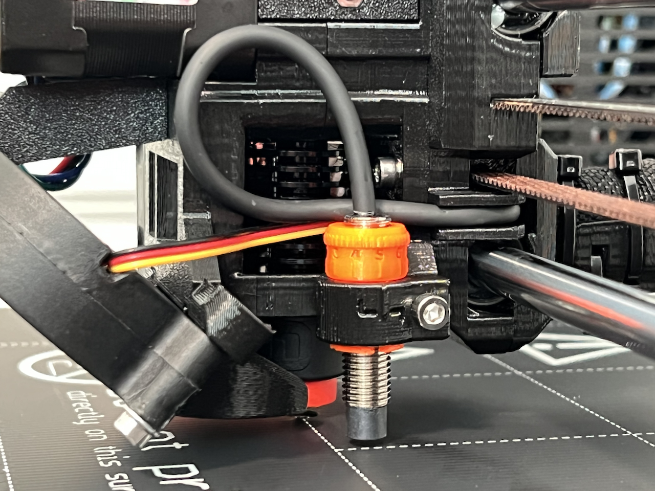
<p>Introducing the SuperPINDA Precision Adjuster! The SuperPINDA Precision Adjuster (SPA) is an integrated mount and adjustment tool for the SuperPINDA probe. This first version is specific to the Prusa i3 MK3S+, however the <i>Drill Bit Version</i> of the MK3S+ SPA will work on both the MK3S+ and the MK3S (and may also work on the MK3, but I have not done any testing at this time); details on the <i>Drill Bit Version</i> of the SuperPINDA Precision Adjuster later in the description.</p><p> </p><h5>The SuperPINDA Precision Adjuster is also available for the MINI/MINI+!</h5><p><a href="https://www.printables.com/model/254166-superpinda-precision-adjuster-for-prusa-minimini"><strong>SuperPINDA Precision Adjuster for Prusa MINI/MINI+</strong></a></p><p> </p><h3>Overview:</h3><p>The SuperPINDA Precision Adjuster is a two-part design, the SPA and a required modification to the MK3S+ extruder body. The SPA allows precise adjustment of the height of the SuperPINDA probe via rotation of the SPA. The SuperPINDA Precision Adjuster also provides a much more secure mount for the SuperPINDA probe when the clamping screw is tightened. No more shifting the position of the SuperPINDA and throwing off your first layer calibration when you accidentally bump it! No more stripping out the M3nS nut hole in the extruder body when trying to secure the probe in place because much less torque on the clamping screw is required to lock the it in place! The body of the SPA has a numbered scale which equates to 0.1mm of height adjustment when used and aligned with the reference mark on the extruder body.</p><p> </p><h4>Printing Considerations:</h4><figure class="image image-style-align-center image_resized" style="width:48.1%;"><img src="https://media.printables.com/media/prints/227763/rich_content/be33c9e5-1752-4581-8d0c-047609dd600c/screen-shot-2022-06-18-at-000026.png#%7B%22uuid%22%3A%220d98b694-1af1-4921-a952-c70a5a6f45c6%22%2C%22w%22%3A1926%2C%22h%22%3A1638%7D"></figure><p>The SuperPINDA Precision Adjuster is printed in PETG at a 0.1mm layer height for better detail/resolution on both the internal threads and the numbered scale on the exterior circumference of the SPA.</p><p>It is highly recommended that you dry your filament thoroughly prior to printing the SPA to reduce the amount of potential stringing which will in turn reduce the amount of post processing/clean up you have to do before installing and using the SPA. Excessive stringing will also clog the threads and prevent the SPA from working properly (it may be VERY difficult to adjust once installed).</p><p>The modified extruder body should be printed in PETG at a 0.2mm layer height with 20% grid infill (this is the recommendation from Prusa).</p><p> </p><h4>Post Processing:</h4><p>Use a hobby knife to clean up any stringing between the quadrant legs of the SuperPINDA Precision Adjuster. Also check the overhang (underside as printed) of the locking pawls on each quadrant leg and trim any bulging/sagging extruded filament with the hobby knife.</p><figure class="image image_resized" style="width:50%;"><img src="https://media.printables.com/media/prints/227763/rich_content/8a0d4a27-716b-461f-a378-f18c4c001f66/img_3021.jpeg#%7B%22uuid%22%3A%224771cee2-596f-4dbc-87fa-af19da63382d%22%2C%22w%22%3A1280%2C%22h%22%3A960%7D"></figure><p><strong>Don't skip this step!</strong> While trimming the stringing between the quadrant legs is more of a cosmetic concern, leaving any bulging/sagging extruded filament on the overhang of the locking pawls will cause excess drag when rotating the SPA inside the holder on the extruder body which will make adjustments difficult. Depending on how well your printer handles overhangs, the bulging/sagging extruded filament may also prevent the SPA from properly fitting into the holder on the extruder body.</p><p>Check the inside surface of the holder on the modified extruder body for any rough spots or stringing and remove or smooth them with a hobby knife, sandpaper, or a rounded file.</p><p><img src="https://media.printables.com/media/prints/227763/rich_content/fbf94ab0-74b9-44de-830a-0891cec2319b/img_3017-3018.jpg#%7B%22uuid%22%3A%22f163f2d2-b6c3-48e0-9cab-cc3d9d3b097d%22%2C%22w%22%3A2560%2C%22h%22%3A960%7D"></p><p>A smooth inner surface on the holder will allow the SuperPINDA Precision Adjuster to rotate easily within the holder when the clamping screw is released, providing effortless adjustment, but… <strong>Don't over do it!</strong> Removing too much material will reduce the clamping force provided by the screw and could result in the inability to properly secure the SuperPINDA probe in place.</p><p> </p><h4>Installation Preparation:</h4><figure class="image image-style-align-right image_resized" style="width:50%;"><img src="https://media.printables.com/media/prints/227763/rich_content/4ec0c7b6-6d9e-4e7a-82c7-b13bdfcf937d/img_3061.jpeg#%7B%22uuid%22%3A%22d8595fc4-9b02-4627-9389-c2939f5ebe55%22%2C%22w%22%3A1280%2C%22h%22%3A960%7D"></figure><p> </p><p>Before tearing apart your extruder to replace the stock extruder body with the modified extruder body, it is important to <strong>test fit</strong> all of the components to make sure everything will fit together nicely in order to minimize the chance of running into any issues while your printer is temporarily out of commission.</p><p> </p><p> </p><p> </p><figure class="image image-style-align-left image_resized" style="width:50%;"><img src="https://media.printables.com/media/prints/227763/rich_content/2df38893-c76b-483e-8f24-8a4afc4cc602/img_3169.jpeg#%7B%22uuid%22%3A%222bb768b2-d5ec-4169-af31-aaba452e4965%22%2C%22w%22%3A1280%2C%22h%22%3A960%7D"></figure><p>If you don't have a spare SuperPINDA probe laying around for test fitting the components and you also don't want to pull the one off of your extruder before you're sure everything is going to fit together correctly, then I <i>highly </i>recommend going to your local hardware store and picking up an M8-1.0x30mm bolt to use for the test fitting process. A bolt length of 30mm is as short as I would go, but longer will work just as well, if not better.</p><p> </p><p>Work the SuperPINDA Precision Adjuster onto and off of the SuperPINDA probe (or stand-in M8-1.0 bolt) several times to “break in” the part. Depending on how the print went, you may only have to do this once, but you may find it necessary to do it several times. In testing, I had some iterations thread onto the bolt easily the first time, and some that had to go on and off five or six times before they began to loosen up. The end result should be that you are able to thread the SPA onto the probe or bolt with minimal effort; we want this to be smooth so adjustments are easy to make once everything is installed.</p><figure class="image image-style-align-right image_resized" style="width:50%;"><img src="https://media.printables.com/media/prints/227763/rich_content/99eb536d-f011-489e-8cca-ae934f36f2e4/img_3022.jpeg#%7B%22uuid%22%3A%227ffd7372-6132-4c73-92de-37029f025033%22%2C%22w%22%3A1280%2C%22h%22%3A960%7D"></figure><p>Next, test fit the SuperPINDA Precision Adjuster in the modified extruder body holder. You will need to spread the holder apart slightly in order to fit the SPA in. The quadrant legs of the SPA will flex together as you insert them into the holder, but there's not quite enough clearance for it to fit through without spreading the holder open slightly. Be careful not to spread the holder open too far or you could break it! Once fully inserted, the SPA should rotate easily within the holder.</p><p> </p><figure class="image image-style-align-left image_resized" style="width:50%;"><img src="https://media.printables.com/media/prints/227763/rich_content/3fb792fb-00d3-42c1-9895-10219ad06e05/img_3026.jpeg#%7B%22uuid%22%3A%220791229e-b774-445b-bab4-b783f369cf90%22%2C%22w%22%3A1280%2C%22h%22%3A960%7D"></figure><p>If the SPA drags on the inside of the holder, remove the SPA (don't forget to spread the holder open a bit as you pull the SPA out!) and check both parts for any debris or rough areas. Smooth out any problem areas you find and try the test fit again. Once you're satisfied with the fit of the SPA in the holder, thread the probe or bolt into the SPA while it's in the holder. The final check is to hold the probe or bolt stationary with one hand and rotate the SPA with the other to verify you're able to easily rotate the SPA, thereby adjusting the height of the probe (or in this case, the bolt).</p><p>After you've completed these pre-assembly steps, it's time for surgery! I hope you've got a stash of Haribo gummy bears nearby…</p><p> </p><h3>Installation:</h3><p>If it's been a while since you assembled your MK3S+ or if you have a pre-assembled MK3S+, I recommend reviewing section 5 of the MK3S+ Assembly Manual, <a href="https://help.prusa3d.com/guide/5-e-axis-assembly_169235">E-Axis Assembly</a> to (re)familiarize yourself with the various parts of the extruder and where they are located in the assembly.</p><p>The following is a fairly condensed set of instructions for swapping the stock extruder body with the modified extruder body and should only be used as a general reference. Swapping the extruder body can be accomplished while the X-axis is installed. I recommend raising the Z-axis toward the top before starting this procedure so you have ample room to work.</p><ol><li>Remove the print fan (tuck it between the X-axis belt and bottom bar).</li><li>Remove the SuperPINDA (lay it over the top X-axis bar or over the X-axis belt, depending on how much cable slack you have).</li><li>Remove the hotend fan (let it hang from its cable).</li><li>Remove the extruder idler.</li><li>Remove the IR sensor cover and IR sensor (no need to completely remove the IR sensor, just remove the screw holding it in place and let it hang off the back side of the extruder by its cable).</li><li>Remove the print fan shroud and print fan support via the two screws below the extruder motor (should come off as one piece).<img class="image-style-align-right image_resized" style="width:50%;" src="https://media.printables.com/media/prints/227763/rich_content/b2facbdf-a02f-4553-8e96-e5e06fd94c68/img_3062.jpeg#%7B%22uuid%22%3A%2283ca14fb-5c33-422a-9ef5-6b55eee46778%22%2C%22w%22%3A1030%2C%22h%22%3A700%7D"></li><li>Have a zip tie on hand, then remove the last screw holding the extruder motor in place (opposite the extruder idler) and use the zip tie to hang your extruder motor off of the top frame or one of the X-axis bars. Be careful not to allow your hotend to fall out as you risk breaking the delicate wires. You should now be at this point (ignore the complete removal of the cable support and textile wrap – I was accomplishing multiple tasks at once):</li><li>Support the hotend to protect the delicate wires (use another zip tie or place an object on the heatbed tall enough to rest the hotend on).</li><li>Remove the extruder body from the X-axis carriage.</li><li>Transfer all hardware and remaining parts (such as the magnetic arm for the filament sensor) from the stock extruder body to the modified extruder body.</li><li>Install the modified extruder body (be sure the SuperPINDA Precision Adjuster is already installed in the holder on the modified extruder body).</li><li>Follow the previous steps in reverse order to rebuild the extruder.</li></ol><figure class="image image_resized" style="width:75%;"><img src="https://media.printables.com/media/prints/227763/rich_content/7700fd70-4592-4110-a7a5-5672079ffb2c/img_3070.jpeg#%7B%22uuid%22%3A%227f1d552c-9bf2-465d-b844-000f061694d4%22%2C%22w%22%3A1280%2C%22h%22%3A960%7D"></figure><p>When it's time to insert the SuperPINDA probe into the SuperPINDA Precision Adjuster, be sure to hold the SuperPINDA to prevent it from rotating and only rotate the SPA (note the directional arrows on either side of the reference mark) to move the probe down close to its final position. <i>Always</i> hold the SuperPINDA with one hand and rotate the SPA with the other while making adjustments. Doing so will ensure proper operation of the SuperPINDA Precision Adjuster and prevents unnecessary stress on the SuperPINDA cable.</p><figure class="image image_resized" style="width:75%;"><img src="https://media.printables.com/media/prints/227763/rich_content/3ab9a920-8eb1-4c89-b96f-2db593eb367e/img_3081.jpeg#%7B%22uuid%22%3A%22fdb43488-a26e-4be6-84d9-5daa5b7037d6%22%2C%22w%22%3A1280%2C%22h%22%3A960%7D"></figure><figure class="image image_resized" style="width:75%;"><img src="https://media.printables.com/media/prints/227763/rich_content/5efb90b8-7292-4e99-a894-d3397205bcb7/img_3082.jpeg#%7B%22uuid%22%3A%221f0b65e5-2398-43f2-a2a1-21270540b64c%22%2C%22w%22%3A1280%2C%22h%22%3A960%7D"></figure><p>After installation of the SuperPINDA Precision Adjuster is complete, simply adjust the SuperPINDA probe as described <a href="https://help.prusa3d.com/guide/9-preflight-check_176167">here</a>.</p><figure class="image image_resized" style="width:75%;"><img src="https://media.printables.com/media/prints/227763/rich_content/50567250-047f-41e6-822c-0b03022cf4ce/img_3113.jpeg#%7B%22uuid%22%3A%229826f285-ae9e-450a-9586-2f0428fe2f42%22%2C%22w%22%3A1280%2C%22h%22%3A960%7D"></figure><p>Secure the position of the SuperPINDA and SPA by tightening the clamping screw. Less torque is required on this screw for a secure hold on the probe than was necessary with the original design. Tightening the clamping screw until the gap in the holder just barely closes provides more than enough clamping force to lock everything in place.</p><figure class="image image_resized" style="width:75%;"><img src="https://media.printables.com/media/prints/227763/rich_content/da49635e-d1df-4930-80dc-8b0a8595659e/img_3191.jpeg#%7B%22uuid%22%3A%22a4472054-7d62-40ed-9bbf-0a2fcee43e3c%22%2C%22w%22%3A1280%2C%22h%22%3A960%7D"></figure><p>If you've made it this far, congratulations and I hope you enjoy your new SuperPINDA Precision Adjuster!</p><h3>Drill Bit Version of the SuperPINDA Precision Adjuster for the MK3S+:</h3><p>For those of you who are intimidated by the prospect of ripping apart your extruder to swap the original extruder body with the modified version for the SPA or if you just don't want to have to go through that amount of effort to use the SPA, I have designed a “Drill Bit Version” (DBV) of the SuperPINDA Precision Adjuster. The DBV SPA can be used with the original extruder body after reaming out the holder with a 13/32" drill bit. The reaming of the original holder can be done in place, however I recommend using a tap wrench or something similar to manually run the drill bit through the holder — a power tool for this application would be overkill. You will also have to remove a bit of the material at the back of the holder, where the holder meets the rest of the extruder body, to make room for the SPA; do this with a sharp hobby knife or a small file.</p><figure class="image image_resized" style="width:75%;"><img src="https://media.printables.com/media/prints/227763/rich_content/dc87c3b3-dc8d-41d7-b9cb-46f08a6c5cdb/img_3192.jpeg#%7B%22uuid%22%3A%22a53ac734-7a42-40e1-8a95-b358b553c9ec%22%2C%22w%22%3A1280%2C%22h%22%3A960%7D"></figure><p>After reaming the hole and removing the little bit of material that interferes, pop in the SPA, adjust the height of the SuperPINDA, tighten the clamping screw and you're off to the races!</p><p><strong>Recommended: </strong>Print a spare extruder body (either the original or the modified version, your choice) <i>before</i> attempting to ream the holder with the drill bit, juuuuuuuust in case things don't go your way during the reaming process. At least then you'll be able to replace the broken extruder body without having to duct tape or glue the SuperPINDA in place while you print a new one.</p><p> </p><h4>Other Considerations:</h4><ul><li>If you plan to use the SuperPINDA Precision Adjuster and you have at all been considering upgrading your hotend to <a href="https://e3d-online.com/products/revo-six">E3D's Revo Six</a>, which is a drop-in replacement, I strongly recommending doing so at the same time you install the SPA, because you'll have already done most of the work required to swap hotends by swapping the extruder body to install the SPA. I chose to do this during my install of the SPA and I'm glad I did.</li><li>Similarly, if you are interested in getting the MMU2S for your MK3S+, the changes to the extruder required for the MMU2S are easy to do while you're installing the SuperPINDA Precision Adjuster. I've had the MMU2S sitting around for a few weeks and was waiting for the right time to build it. I was unaware that the MMU2S required changes to the extruder and almost decided to hold off and just install the SPA by itself, but I started poking through the assembly manual for the MMU2S and realized there were changes that needed to be made to the extruder, so I ended up doing everything at once; I'm glad I did because it worked out really well.</li></ul><p> </p><h4>Change Log:</h4><ul><li>01AUG2022 – Updated SPA model files to include PrusaSlicer settings.</li><li>10AUG2022 – Minor changes and/or additions to some of the wording in the description.</li><li>11AUG2022 – Added link to the newly-released <a href="https://www.printables.com/model/254166-superpinda-precision-adjuster-for-prusa-minimini">SuperPINDA Precision Adjuster for the MINI/MINI+</a>.</li></ul>
With this file you will be able to print SuperPINDA Precision Adjuster for Prusa i3 MK3S+ with your 3D printer. Click on the button and save the file on your computer to work, edit or customize your design. You can also find more 3D designs for printers on SuperPINDA Precision Adjuster for Prusa i3 MK3S+.