SUPPORT FRAME WITH MOBILE TABLET
thingiverse
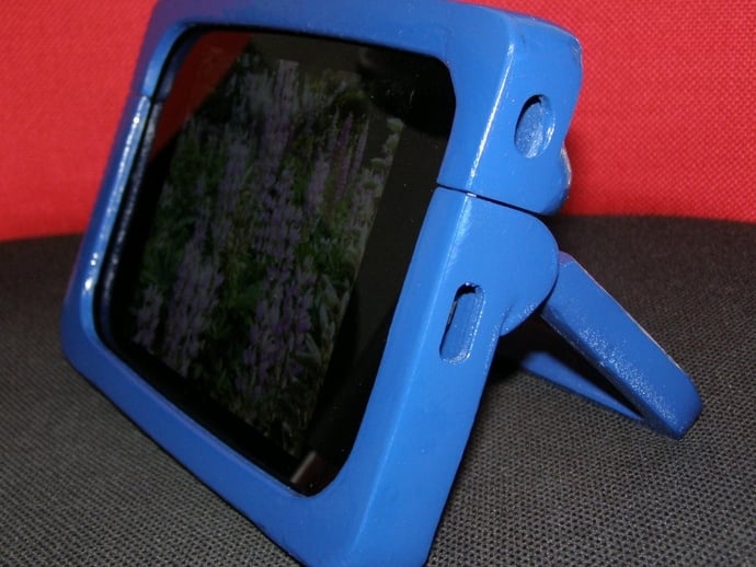
Support Frame for Mobile Tablet The portable version of a tablet car support was developed based on the original design, with some modifications. The project utilized a Nexus7 tablet with dimensions 195x120mm. The creator found the support comfortable and decided to develop another portable mode with innovative features. Key innovations include a handle that allows three positions: vertical standing, inclined viewing of other videos, and a more inclined position for typing. A unique feature is the system fit between two parts of the frame - top and bottom - joining via a dock. Two pins on the upper frame's protrusion fit into a cavity in the lower frame, forming a single tablet frame. The locking handle mechanism consists of three holes at different angles on its head to allow three positions. To maintain stability, two shields are located on both sides of the bottom frame to secure the handle. The assembly process ensures that the handle remains fixed in any chosen position. Three main parts make up the frame: the top frame fits onto the bottom frame via a fitting, includes a drawer for the headset, and has a niche to support a smartphone or tablet. The lower frame is supplemented by the upper frame, connected with the handle through side pins that fit into holes in the handle's head, locking it in place. A metallic pin (5x14mm) provides reinforcement. Additional auxiliary parts include a bulkhead for handle support and prevent loosening. After assembly, the frame can guard the tablet while carrying and protect the screen when turned to the opposite direction. The original design faced imperfections like warping and cracking, requiring epoxy putty repairs. The designer added two side screens to support the handle and a drawer for the headset as another support feature. To create this project, tools like a micro drill, sandpaper, epoxy putty, glue, pliers, spray paint, etc., are required. Photos of the completed assembly can be sent by the creator, and any questions or concerns should be directed to isarts3d@gmail.com.
With this file you will be able to print SUPPORT FRAME WITH MOBILE TABLET with your 3D printer. Click on the button and save the file on your computer to work, edit or customize your design. You can also find more 3D designs for printers on SUPPORT FRAME WITH MOBILE TABLET.