Switching dual extruder - easy upgrade
thingiverse
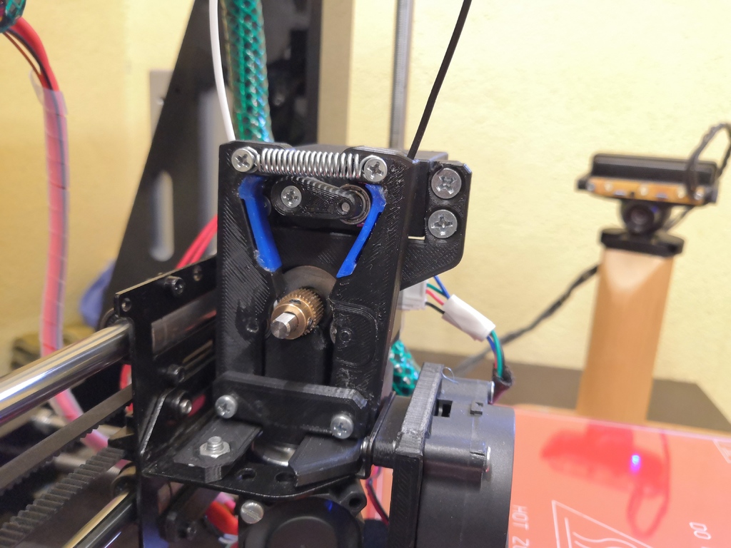
**Update:** I had problems with the idle filament slipping out of the lever. Therefor I changed the lever a bit. Since the servo pushes the idle lever away I decided to use this force to hod the idle filament in place. The updated lever now contains a flexible part where the servo pushes on the leverarm that is deformed under this force and therefor jams the filament in the path. For building the extruder there are no major differences. Just use the new lever (lever_new.stl and brake.stl) instead of the old one. I printed the brake.stl in TPU for allowing it to flex under the load. For assembly of these two parts I used a PVC glue. Everything that is explained here in the following can be downloaded as an Installation-Guide that is attached in the ThingFiles # What? This Design is a switching dual extruder that uses a single hotend. It is a replacement for originally built-in extruder. The switching extruder is built for a Geeetech Prusa i3 pro B printer and its X-axis carriage. Nevertheless, this design can be altered quite quickly to suit any other printer. The extruder is fed with two filaments which can automatically be loaded or retracted. Therefore you can equip a normal printer relatively easy with a second extruder. The extruder is made with the Marlin Firmware in mind. Of course you can use it with every other Firmware that supports this kind of switching mechanism. # Why? The intention was to build an extruder that is easy to build, low-cost and doesn´t add much weight to the printhead. I don´t print with two colors quite often, but now and then I need to. Up to now I used the M600 command of the Marlin Firmware that lets you change filaments midprint by hand. Unfortunately, with many color changes, this procedure can be very time consuming. # Step 1: Build Extruder ## What you need: - printed parts (download here from Thingiverse) - 1x base plate - 2x bearing disc - 1x clamp - 2x lever - 2x lever pin - 2x lever plate - 1x motor plate - 1x servo lever - 4x servo spacer - 2x spacer - 5x bearings (623.ZZ or similar dimensions) - 8x M3 x 10 countersunk screw - 2x M3 x 30 countersunk screw - 2x M4 x 10 flat head screw - 4x M4 x 20 countersunk screw - 2x M3 hex nut - 6x M4 hex nut - 1x servo (MG996R or similar dimensions) - 1x tension spring (spring rate approx. 2 N/mm, length 16mm) - 1x hotend E3D-V6 - 1x Nema 17 stepper motor - 1x extruder drive gear - Some glue ## surrounding: carriage Geeetech Prusa i3 pro B For different printers the adapter plate may need to be altered to suit the specific printer ## assembly For most of the steps I uploaded a matching picture. 1. Print all parts 2. Put together both levers (see the attached pictures). Use glue to connect the parts. 3. Mount the extruder drive gear on the shaft of the stepper motor. 4. Screw one of the bearings to the servo lever 5. Press the servo lever on the shaft of the servo. Secure it with one of the M3 x 10 screws. The angle you press it on the shaft is not important at the moment. We can set the right angles in the firmware later. 6. Mount the servo to the motor plate. Use the M4 x 20 screws and nuts. Put the servo spacers between servo and motor plate to ensure the right distance. 7. Screw the motor plate to the NEMA17 using 4 of the M3 x 10 countersunk screws 8. Insert two of the M4 nuts in the base plate 9. Insert the E3D-V6 hotend from the bottom in the hole in the X-carriage of the printer 10. Slide the base plate over the groove in the E3D-V6 11. Connect the base plate with the extruder carriage using the M4 screws 12. Slide the M3 x 30 screws through the clamp. Next slide the pre-assembled levers onto the screws. Slide the spacers onto the screws. 13. Place the pre-assembled motor/servo assembly on top of the hotend. 14. Add the pre-assembled lever assembly. 15. Add the spring to the assembly. Use the bores on top of the levers. Start with the holes in the middle. If the filament slips through you need more tension on the spring. If the extruder starts skipping steps the tension on the spring is too high. # Step 2: Electrical connection to printer As the hardware is now completed, the next step is to connect the extruder to the printer. Plug the cable of the NEMA17 into its port on the Mainboard. Make sure to only connect the stepper while the mainboard is not powered. Next plug the servo into its port on the Mainboard. If your mainboard doesn´t have a servo port, you can use any free signal pin together with a VCC and GND pin. The signal pin just needs to be declared in the firmware as shown in Step 3. # Step 3: Firmware Configure the configuration.h file of the Marlin firmware as shown here: I used Marlin 2.1.2 for this example. All lines are under the ‘getting started’ section. // This defines the number of extruders // :[0, 1, 2, 3, 4, 5, 6, 7, 8] #define EXTRUDERS 2 // For Cyclops or any "multi-extruder" that shares a single nozzle. #define SINGLENOZZLE // A dual extruder that uses a single stepper motor #define SWITCHING_EXTRUDER #if ENABLED(SWITCHING_EXTRUDER) #define SWITCHING_EXTRUDER_SERVO_NR 0 #define SWITCHING_EXTRUDER_SERVO_ANGLES { 265, 5 } // Angles for E0, E1[,E2, E3] #if EXTRUDERS > 3 #define SWITCHING_EXTRUDER_E23_SERVO_NR 1 #endif #endif The SWITCHING_EXTRUDER_SERVO_ANGLES may need to be altered, depending on how you pressed the lever on the servo. Choose the angles in a way the lever is horizontal in both final positions. If you have probes or something similar mounted on your extruder, make sure the distance between the nozzle and the probe is right. You may need to change the distances in the according section in the firmware. If your board is equipped with a servo socket you can just plug the servo in and you´ll be good to go. If your board doesn´t have a servo socket or it is already used for something else, you can bypass this problem by using a free pin on another socket. This pin has to be declared as the servo pin by editing another file of the firmware. Under …\Marlin-2.1.2\Marlin\src\pins\ search for your Mainboard. Open the according file and change // // Servos // #define SERVO0_PIN PA1 // SERVOS Search for a pinout of your board and write the right pin number as the SERVO0_PIN. #Step 4: Slicer The last step is to configure your slicer. First I tried to use Cura. Unfortunately, Cura does not support dual extruders that share the same nozzle very well. The main problem here is the wipe tower that doesn´t work the way it should. Also there are near to no settings available for unloading the filament properly. Therefor I switched to the PrusaSlicer. Since Prusa offered the MMU1 (“Multi Material Unit”) some years ago, which has a very similar concept like this switching dual extruder, they added support for this in their slicer. All these included settings can be used to our advantage. To setup the slicer do the following steps: 1. Add a new printer 2. Set up all settings according to your needs. The printer should be able to print flawless with one extruder. 3. After you are confident enough that your slicer profile works for printing with one extruder you are ready to alter the profile for the second extruder. 4. Under the Tab “Printer Settings / General” in the section “Capabilities” set the number of Extruders to two and check “Single Extruder Multi Material”. (see picture attached) 5. Under the Tab “Printer Settings / Single Extruder MM setup” set everything as shown in the picture attached. A short explanation what these numbers do: At unloading the filament is pulled out quite fast for 30mm. There it sits for a short time and gets moved back and forth by 5mm. After that the filament is pulled out to its final destination at 59 mm. When loading the filament it is not only pushed in by 59mm but by extra 2mm to purge the nozzle. 6. Under the Tab “Filament Settings / Advanced” in the Section “Toolchang parameters with single extruder MM printers” set as seen in the picture attached. These are the settings how exactly the printer has to load and unload the filament when switching between the extruders. 7. Load your Model into PrusaSlicer and assign both materials. Prusa provides a quite helpful database on their website on how to use all the features in their Slicer that are related to multi-material-printing. https://help.prusa3d.com/de/category/multi-material-slicen_881 8. After changing the filament there is some residue left in the nozzle. This needs to be pushed out with the new filament. Extrude the wrong filament. Then change to the filament you want to measure the volume for. Extrude a known length of filament (PurgeLength) and observe the strand coming out of the nozzle. Repeat this procedure until the strand out of the nozzle gets pure. Then calculate the volume with following formula Volume = (FilamentDiameter / 2)² * PI * PurgeLength Under the Tab “Plater” click on the button “Purging Volumes” on the right hand side. Enter the calculated number like shown in this tutorial: https://help.prusa3d.com/de/article/reinigungsvolumen_125097 Now you have successfully setup your switching dual extruder. Congratulations!
With this file you will be able to print Switching dual extruder - easy upgrade with your 3D printer. Click on the button and save the file on your computer to work, edit or customize your design. You can also find more 3D designs for printers on Switching dual extruder - easy upgrade.