T-Slot USB Power Housing
thingiverse
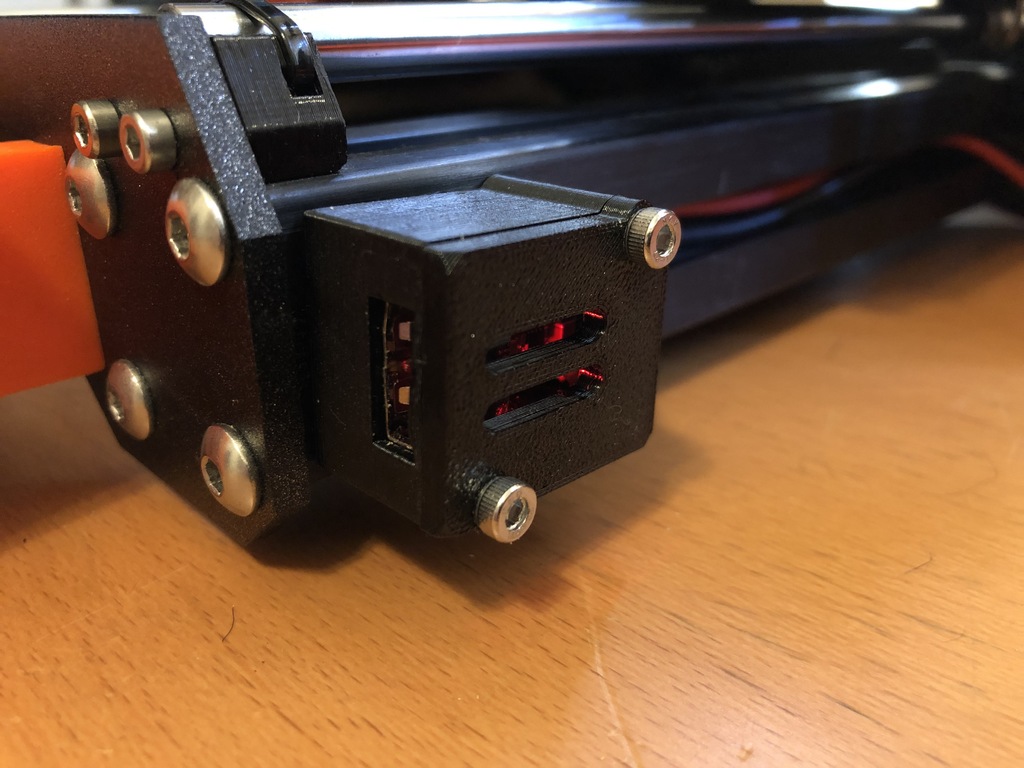
Here's a nifty enclosure so you can add a USB power port to the t-slot rails on your printer, cnc machine, etc. Why might you ask? Like you need another port to charge your phone? The answer is pretty simple. I didn't like the idea that I had to have two power cords for one printer. See, I have an Octoprint server attached using a Raspberry PI. It's powered by USB and my sense of order doesn't like messy cabling. A little playing on OpenSCAD and, problem solved. Oh, and you can also use it to charge your phone. BOM: 1 . HW-384 DC DC Step Down Module / USB Buck Converter Board. Here's a link to a five pack: https://www.amazon.com/gp/product/B01HXU1C6U/ref=ppx_yo_dt_b_asin_title_o01_s00?ie=UTF8&psc=1 (If you can't use Amazon, Google the part number "HW-384" or "HW384," it will come up.) Silicone insulated 16ga Wire, because Silicone. (PVC insulated wire will also do, 16ga is a bit overkill, but why not?) A few Inches is all you need. Here's a link for to way too much: https://www.amazon.com/gp/product/B00TG1TRL2/ref=ppx_yo_dt_b_asin_title_o00_s00?ie=UTF8&psc=1 2 #10 insulated fork connectors. Grab an assortment, you'll need them one day: https://www.amazon.com/Glarks-240pcs-Terminals-Connectors-Assortment/dp/B01E5V5GMG Appropriate T-Slot M3 Hardware I got mine from Thingiverse: https://www.thingiverse.com/thing:3199057/files Cable clips for wire management. For mine, I used this: https://www.thingiverse.com/thing:2639102 2 M3x10 Screws for the lid 2 M3x10 Screws to mount it with. 2 M3 hex nuts - if you print the T-slot M3 hardware from Thingiverse Tools Crimping Tool / Wire Stripper Philips Screw Driver Soldering Supplies M3 Allen Wrench Time. Notes: Tolerances are TIGHT. This is so the board doesn't move around when you connect a USB cable. Once the enclosure is mounted to your printer, prepare to solder the wires to the top of the module. The Negative/Black pad is the one which is connected to the ground plain on the bottom of the board. Strip a small amount of insulation (1/8"/ 3mm) from the end of the wire you are going to solder to the board. Tin the pads on the board and on your wire first. Be *Careful* about shorting to any components on the board. Space is at a premium on it. See pictures. Gently bend the wire as shown so it will fit through the hole on the back of the enclosure. After that, thread the wires through the hole on the back of the enclosure, then insert the FRONT of the module, ANGLE DOWN, so the USB port lines up with the hole on the front of the enclosure. You might need to use a small flat head screwdriver to shoe horn the USB port in to the hole. Once that's done, press down the back of the board while threading extra wire through the hole until it's seated. Screw on the lid, crimp the fork connectors to the wire, then finish connecting it to your power supply. Connect it to the same power supply terminals you are using for your controller, don't use the ones for the heat bed if applicable. Some power supplies have an extra set of terminals, use those if you are lucky enough to have them. A little cable management, and you are done. I've included the OpenSCAD file so you can tweak it and clean up some of my quick and dirty code if you feel like it. I tested this with a load up to 2.5 amps. That's about two and a half times what a raspi uses for Octoprint with a 3.5" LCD Screen. It gets pretty hot at higher loads. If you are planning on using it that way, think of using ABS or another higher temp plastic to print it.
With this file you will be able to print T-Slot USB Power Housing with your 3D printer. Click on the button and save the file on your computer to work, edit or customize your design. You can also find more 3D designs for printers on T-Slot USB Power Housing.