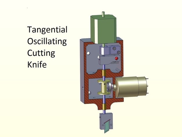
Tangential Oscillating Cutting Knife
thingiverse
The text describes a process for setting up and calibrating a cutting tool, specifically a TOCK, for use on cardboard materials. The process involves several steps, including: 1. **Assembly of the Tool**: Assemble the tool's components, including the cutting head, DC motor, and control box. 2. **Setting Zero Z Level for Cutting/Creasing**: This involves finding the lowest cutting point where the knife just barely touches the base material (soft plastic or rubber) when the head is moved down slowly while oscillating. The contact should be slight to ensure easy cut details. 3. **Adjusting Creasing Level**: After setting the zero Z level, adjust the creasing level by moving up until the knife barely cuts the top layer of cardboard without cutting through both layers. This setup ensures that when the tool performs a partial cut for creasing, it effectively folds the cardboard without tearing. 4. **Setting Axis A (Rotation) in Mach3**: For the tool to function correctly with GCode generated by the program, certain settings within Mach3 must be adjusted. These include disabling angular mode for the A axis and enabling constant velocity mode. 5. **Motor Tuning for A Axis**: This involves setting the steps per mm so that 1mm movement on the A axis yields a 360-degree rotation of the cutting head. The steps per mm are calculated based on the motor's steps and microsteps settings. 6. **Saving Axis Settings and Ensuring Homing for A Axis**: After making changes in Motor Tuning, it's essential to save these changes within Mach3. If there isn't homing for the A axis, either set up a manual process or use jogging to rotate the head to zero angle manually before setting the current position as zero. 7. **M101.m1s Macro for Switching Cutting Motor**: Ensure that the macro file contains necessary code for switching on/off the cutting motor according to Mach3 GCode commands (M07/M08/M09). These steps are crucial for accurately and safely operating the TOCK tool, ensuring precise cuts and folds in cardboard materials.
With this file you will be able to print Tangential Oscillating Cutting Knife with your 3D printer. Click on the button and save the file on your computer to work, edit or customize your design. You can also find more 3D designs for printers on Tangential Oscillating Cutting Knife.