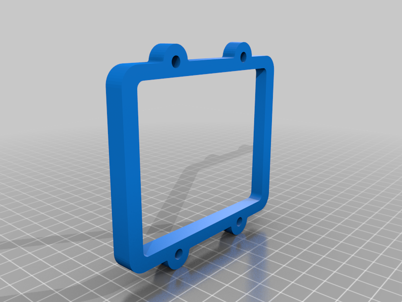
Tapered Outlet Switch box spacer
thingiverse
Don't download the .stl files, they are just examples to get this thing published. Download the .f3g files to your Fusion360. I needed switch and outlet spacers to fix the outlets and switches in my house. All of the great designs here on Thingiverse gave me lots of ideas. And initially I downloaded and printed the Electrical Outlet Box Extender that "someusernamehere" designed because I liked the location tabs. BUT, all the electrical boxes in my house are recessed from the front of the drywall (thus the need for spacer) and are NOT a constant depth. So I need to made a custom angled spacer for each box. Which was a bit of work, and I needed to do it relatively easily. I figured out in Fusion 360 that you can extruded to an Object, which can be a plane, at an angle. So I added two sketches which define the height of the corners and defined a plane through 3 of those corners. So the plane is at an angle to the base sketch (sketch 1). So if you want to make these angled or tapered box spacers you have to 1. Take Calipers and measure the depth that the 4 corners of your switch box are recess back from the drywall surface. In mm. Make a quick sketch (simple rectangle) so you know the location of each corner depth. 2. in Fusion 360 Edit Sketch 4. Tilt the drawing slightly so you can see clearly which corners vs the orientation of the spacer. Double click on the line dimension at each corner and enter your depth number for that corner. It matter that you get the corner depths correct as you go clockwise or CCW around the spacer, specifically for the spacer with tabs. Save the sketch. The single, dual, and triple switch spacers with no tabs you just need to have it correct CW or CCW, the spacer can flip in installation. 3. Do the same for Sketch 5. Again tilt the drawing slightly, noting that you have the right corner vs the model orientation. It can get a little confusing. Save the Sketch 4. The spacer should automatically be tapered to match the corner height because the angled plane adjusts with those heights and then the extrusion adjust automatically also. If it doesn't look right edit lane 4 from the time line and redefine the 3 corners. 5. Save that file. I just over wrote the old one. 6. Export the .stl file, I put in the corner heights as the file name so I can tell the spacer files apart. Example "6.8 5.5 5.4 4,7 Single spacer.stl" When you import the .stl file into your slicer, you'll need to rotate the Single no tabs, Dual & Triple spacer 90 degrees to get it flat on the print bed. NOTE which side is the flat side vs the tapered side and put the flat side down. If you slice and you get supports or your brim is in the middle of the print, the part isn't flat, so flip it 180 degree (X or Y). The single box spacer with tabs is a little trickier, because taper side is opposite the tabs, and it doesn't lay flat (in PrusaSlicer). So: 1. flip it 180 degrees 2. Rotate the X direction while looking at the corner that is too high. use 1 degree steps, then 0.1, then 0.05 degree (+ or -) to get it to lay flat in X. If you watch the bottom and top frame lines you can see them go up or down. If you are lowering that corner, and the top line goes up, you went to far, so raise that corner by 0.05 degrees 3. Then do the Y direction in the same way. The dual and triple spacers are my design. The single is a remix of 5473587. Printed with PLA, 2 perimeters and 20% infill of triangles.
With this file you will be able to print Tapered Outlet Switch box spacer with your 3D printer. Click on the button and save the file on your computer to work, edit or customize your design. You can also find more 3D designs for printers on Tapered Outlet Switch box spacer.