Temperature Controller for your Enclosure
thingiverse
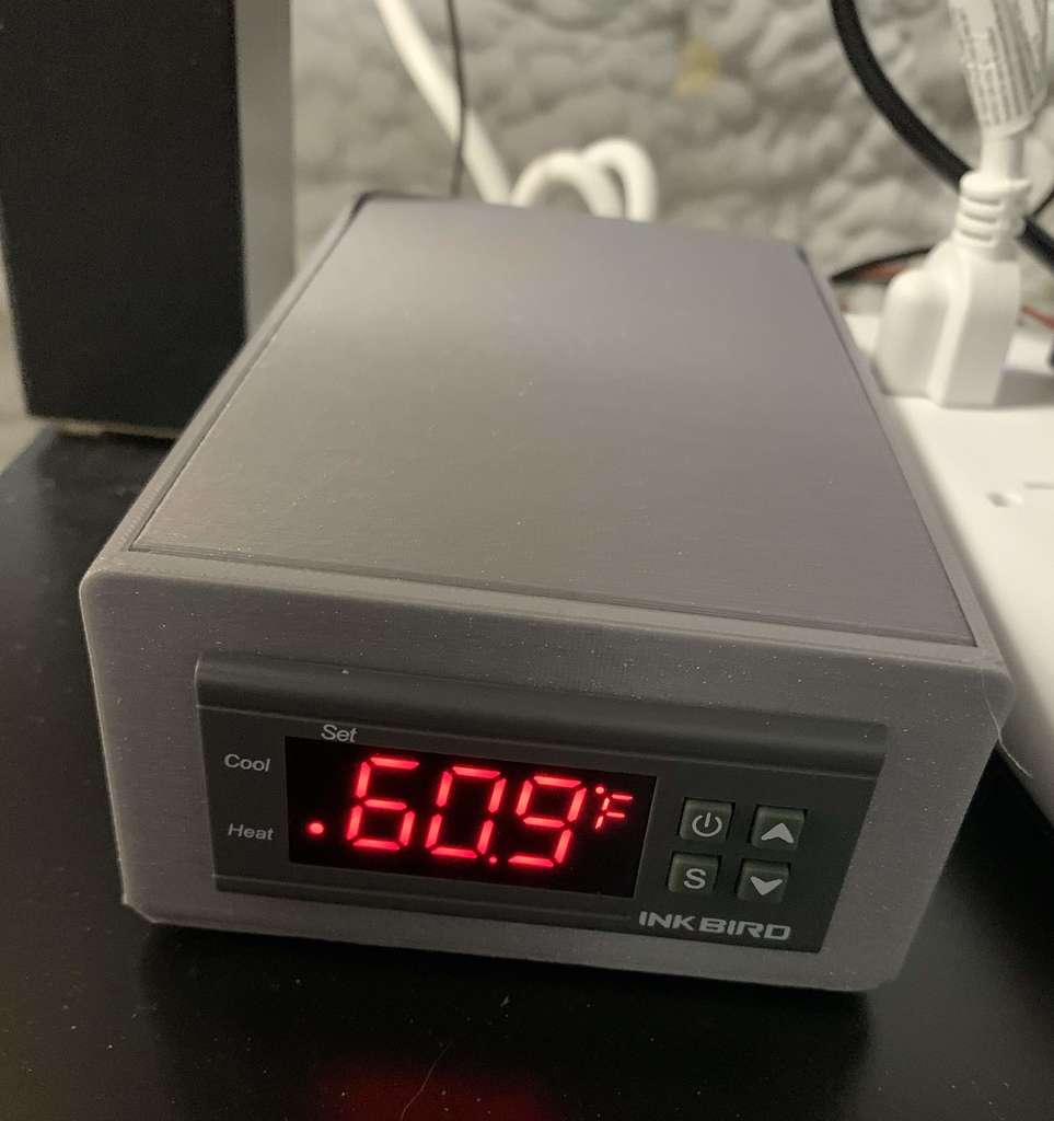
This is a temperature controller for your enclosure using off-the-self electronics components and a printable case. I have found significant improvements in print quality using both an enclosure and temperature control, especially if you print in unheated rooms (my printer is in an unheated basement in New England). You can set a desired temperature in either F or C and the controller will heat and cool to maintain it well. I use a heating element with fan for heating, and a cooling fan for cooling. For higher-temp filaments (like ABS or PETG), printing with enclosure door closed is ideal. For lower-temp filaments (like PLA), you may find it best to print with the enclosure door open - as the cooling fan may have trouble overcoming the heat coming off the nozzle and/or print bed. My instructions below assume 120V AC. You'll need to adapt if you are running 220V. Here's what you need: 1. Inkbird ITC-100F temperature controller (https://www.amazon.com/dp/B00OXPE8U6?psc=1&ref=ppx_yo2_dt_b_product_details) 2. 110V AC heating element with fan (https://www.amazon.com/dp/B07NYX5DKD?psc=1&ref=ppx_yo2_dt_b_product_details) 3. USB cooling fan (https://www.amazon.com/dp/B07ZJ47Z2J?ref_=cm_sw_r_cp_ud_dp_KW4NHTFY702HJ68VPEWG) 4. USB break-out board (https://www.amazon.com/dp/B01MRJYGVM?psc=1&ref=ppx_yo2_dt_b_product_details). This is used to connect to the USB cooling fan above. 5. AC-5V DC converter for cooling fan (https://www.amazon.com/dp/B07YXN8J6R?psc=1&ref=ppx_yo2_dt_b_product_details) 6. AC-12V DC converter for heating fan (https://www.amazon.com/dp/B07SJRX9R6?psc=1&ref=ppx_yo2_dt_b_product_details) 7. Four pan-head phillips-head sheet metal screws (I used #6 3/4 inch) 8. Heavy-duty outdoor extension cord 9. Cable ties (or alternative way of fastening PCBs to the box) 10. Some wire and solder (I used 18-gauge wire, some jumper wire for smaller components) 11. Your favorite type of electrical junctions. I used WAGO lever-nuts, which are easy to add and remove (https://www.amazon.com/dp/B0973FLG4Y?ref_=cm_sw_r_cp_ud_dp_R99W2HYS6NTW77389GVY). This is great for assembling and disassembling the wires to ensure everything works before final assembly. Here are the assembly steps: 1. Print all the parts. I recommend PETG for the temperature sensor stand, in case you print at high temperatures - since the stand will be inside your enclosure. The other parts are outside your enclosure, so use whatever material you like. 2. Cut your extension cord to the desired length. Peel back the outer casing to find the 3 AC wires within, and strip the ends of each. Here's a handy chart to know which wire is which: https://www.allaboutcircuits.com/textbook/reference/chpt-2/wiring-color-codes/. Be careful to correctly identify the proper wires. 3. Solder wire for the heating element, AC-12V DC converter, and heating fan. Note that the heating element requires 110V AC while the heating fan requires 12V DC. Give yourself plenty of extra wire to the heating element & fan, since you may want room to position it where you want in the enclosure. For the AC-DC converters, it doesn't matter which AC wire (hot or neutral) you solder to which AC-in terminal. 4. Solder wire for the AC-5V DC converter and USB break-out board. The pins on the USB break-out board are well marked. You'll only need to solder the VCC and GND terminals. 5. Pull the temperature sensor into the sensor stand - so it stands upright. 6. I recommend connecting all wires as indicated in the wiring diagram - temporarily in order to test that the system works when you plug it in. Then disconnect for assembly. 7. Assemble the parts into the box as indicated in the assembly diagram. Make sure to run the extension cord, heating element wires, and heating fan wires through the circular opening in the back of the box lid first. That way you will be all set to screw the box lid later. Since I am lazy, I opted to use cable ties to fasten the temperature controller, and AC-DC converters to the bottom of the box. The USB break-out board will be held in place by the 2 posts in the print - so it doesn't need to be fastened. 8. Connect all wires as indicated in the wiring diagram. This is where I found the lever nuts helpful so I could disconnect and reconnect wires when making a mistake. 9. Use a cable tie to fasten the extension cord, heating element wires, and heating fan wires to the bottom of the box. 10. Screw-in the box lid. 11. Place your temperature sensor, heating element & fan, and cooling fan where you want in the enclosure. Be mindful not to place anything (like printer parts) too close to the heating element, as it gets really hot up to 5-6 inches away. 12. Plug it in, configure your temperature sensor as per the controller instructions, and enjoy high quality prints!
With this file you will be able to print Temperature Controller for your Enclosure with your 3D printer. Click on the button and save the file on your computer to work, edit or customize your design. You can also find more 3D designs for printers on Temperature Controller for your Enclosure.