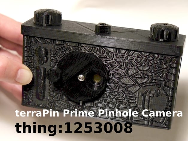
terraPin Prime 6X6 Pinhole Camera -120 Film
thingiverse
A new terraPin Pinhole Camera: fewer parts, fewer vitamins, easier to build. If you have been hesitant to print, assemble, and shoot any of the Schlaboratory 3Dprinted pinhole cameras, this is the camera for you. Only 4 parts to print for the body and shutter assembly, with a variety of winder options. Fewer bolts (can be M3 or 4-40), more Gaffer's tape. Frame 6X6 "Focal Length" 26.75 mm Angle of View 90 degrees nominal horizontal/vertical Designed for 0.23mm diameter pinhole f/116 - f168; nominal f/135 All sample photographs are 6X6 format; view at full screen. I will post all photographs I make with this pinhole camera on Flickr, HERE See terraPin High-Strength Winder (1/4" shaft) for additional winder/knob options! ATTENTION This work is licensed under the Creative Commons - Attribution - Non-Commercial license. This license applies only to the files and documents available for download from the Thing Files section of this Thing.All other related content (photographs, videos, and verbiage such as contained in "Description" or "Instructions" ) are excluded from this license, with all rights reserved, unless specifically available for download This notice constitutes a clarification, not a change, to licensing for this design. Print Settings Printer Brand: LulzBot Printer: TAZ 4 Rafts: Doesn't Matter Supports: No Resolution: 0.25 Infill: =33% Notes: Like all Schlaboratory pinhole camera designs, no support settings are necessary to get an excellent print. Post-Printing Parts to Print There are several body styles, a Voronoi-textured body, a pipped body, and a plain body. Both are available as plates of parts. If your printer bed is large enough, there are two complete plates of all the parts you will need for either version. If your printer is smaller (or you don't like long print jobs), you can print the body plate of choice and the small parts plate. All unique parts are available for download here, and parts common to other terraPin pinhole cameras (knobs, winders, etc), can be downloaded from the terraPin 6X6 page. Vitamins, Equipment, and Finishing Handy tools: -Mill file for smoothing parts -X-acto blade -1/8-inch drill bit -Wrench/tools for fasteners -Razor scraper -Super glue -Bamboo Skewer (or similar) for positioning bits of tape inside the body Vitamins: -16mm M3 hex head bolt for use with lid closure knob (socket head may be substituted). -M3 nut to go under "flipper", which secures the lid. -8mm M3 pan head (low profile) nut for shutter pivot -M3 Lock nut for shutter pivot (Metric hardware can be replaced with 4-40 SAE if desired) -14mm transparent disc for frame indexing hole (office supply stores usually carry transparent colored portfolios/report binders) Gaffer tape, 1-inch wide, used for: -Covering tripod thread inside camera, 1.5 inches -"Holga Flap" over frame indexing hole, back of camera, 3 inches -Pinhole attachment inside body, 1 inch -Covering Lock nut inside body, 0.5 inch (in the absence of Gaffer tape, any opaque black tape that will adhere to your camera may be used. If you are interested in building more pinhole cameras, a roll of Gaffer tape is a great investment.) Pinhole, 0.23mm diameter, provides nominal f/135 Shutter Assembly The shutter requires careful assembly for best results: -Prepare the holes in the shutter disk and front of the camera with 1/8 inch drill bit. Best results to be had with a handheld, slowly turning drill bit. -With the file, carefully smooth the face of the round shutter mount on the front of the camera. Take particular care to flatten the face surrounding the pinhole opening and pivot bolt hole. -Take care not to damage the shutter stop nubbin at the bottom of the shutter mount. -Ensure that the bottom surface (as printed) of the shutter disk is completely flat. Remove any ridges, seams, or irregularities created by the print bed surface. A razor scraper is an excellent tool for this. The shutter is fastened to the front of the camera body with the 8mm bolt and locking nut. Carefully tighten the preload on the shutter to your preference. You will want the shutter to move smoothly, but not accidentally. You may find that a bit of tape is useful to keep your shutter from opening between exposures. About that pinhole.... Even though the pinhole is the most important part of this camera, making the pinhole is not as critical as you might imagine. Any very thin metal can be used, soda cans being a standard source of sheet stock. I use 0.001 inch thick brass shim stock with great results. You will find fine sandpaper (>=400 grit) and a magnifier essential for this. THIS ARTICLE details the methodology I use to make precision pinholes for my cameras. If your pinhole isn't precisely 0.23mm, you can still get completely acceptable results with some experimentation. You may need to slightly adjust the recommended durations on the provided exposure times table. The pinhole is mounted inside the camera body with gaffer's tape, carefully centered in the shutter opening. Take your time here, you want the pinhole precisely centered to avoid peripheral vignetting. Another small bit of tape can be used to cover the shutter nut after the pinhole is mounted. Red Windows and Some Gaffer Tape The 6X6 frame is indexed, when advancing the film, through the window in the rear of the camera body. Traditionally, the frame number is read through a red plastic window. The 14mm translucent disk is glued into a recess in the back of the camera body (but could possibly be taped into position). Just a few small dabs of glue should suffice. Too much super glue here will precipitate on your window, fogging it. I think it is prudent to use a length of tape to cover the indexing window during use. This keeps extraneous light out of the camera body and minimizes the risk for light leaks and fogging your film. Body and Cap Final Cap Assembly: The cap requires preparation with a 1/8 inch drill bit, like the shutter pivot. Gently enlarge the central hole for the lid bolt. The winders are assembled from knobs, winder spades, and baffles. The knob should fit with a snug friction fit on the winder spade. There should be some resistance while turning the knob - this keeps your film from unwinding during use and keeps your frames indexed. Refer to illustration. Final Body Assembly: The "Flipper" is the rectangular plate that swings into position in the top of the camera body. The Flipper will need to be drilled out in like fashion to the lid, with the 1.8 inch drill bit. There is a recess under the Flipper for a M3 nut, secured with super glue. I like to use a bit of tape, in addition to glue, to retain the nut in the event that it is knocked loose. When all other interior assembly is completed (tripod hole taped, shutter and pinhole mounted and taped, the Flipper can be installed. I call this design a "swinging lock joint". The Flipper is inserted into the top of the camera body, into the recesses in the dividers to each side of the central frame. The nut will be on the bottom of the Flipper. Swing the Flipper up toward the front of the camera until you can thread the lid-securing bolt into the nut under the Flipper. GENTLY pull on the bolt, while coaxing the Flipper over the small ledge at the front of the camera body. The front of the camera body will flex outward as the Flipper swings up. If the front edge of the camera body is not straight after installing the Flipper, the Flipper is not quite in place. Revisit. Refer to illustration. When securing the lid to the body, it is important not to push on the nut, unless you want it rattling inside your loaded camera. Notes on Shooting the terraPin Prime Because this camera has such a shallow "focal length", there is considerable variation in the distance from the pinhole to the film, at the center of the frame and the corners. I have had great results using an f/number calculated from a spot halfway between the center and edge. Technically, the center will be a little over-exposed and the corners under-exposed, and this optical vignetting is a classic pinhole camera effect. Refer to the frame mapping for more information. Film may be loaded and advanced to your preference on either left or right side. 120 film is notorious for unrolling during unloading and such a "fat roll" will cause photo-fogging light leaks and heartache. Included in the parts is a film clip that fits diagonally inside the camera, around the TAKE-UP spool. The clip will be snug around the exposed roll of film when you unload the camera. Like all the terraPin pinhole cameras, the shutter mech allows for a "digital" shutter - there is a detent into which you can place your finger while opening the shutter. If you need a relatively short exposure, you can use your finger as the shutter without the attendant jostling that rotating the shutter plate may cause. Take your time, and it is an easy technique to master. It's beyond the scope of this forum to go into detailed instructions regarding pinhole photography, but I refer you to the User's Guide I wrote for the P6*6 3D printed pinhole camera. Lastly, if you have gotten this far, and still have questions, PLEASE post in the comments section. I look at my Thingiverse feed EVERY DAY, and I am very responsive to user's questions. Your question may help someone else too! How I Designed This This was designed almost entirely in Tinkercad, a deceptively simple, but capable online CAD application. The 3D printed 1/4-20 tripod threads were modeled in OpenSCAD, eliminating a piece of non-printed hardware. In testing, the printed threads (PLA) seem to be robust enough for repeated use. The Voronoi texture is from a native Tinkercad shape generator. The pips were parametrically modeled in OpenSCAD.
With this file you will be able to print terraPin Prime 6X6 Pinhole Camera -120 Film with your 3D printer. Click on the button and save the file on your computer to work, edit or customize your design. You can also find more 3D designs for printers on terraPin Prime 6X6 Pinhole Camera -120 Film.