CR-10S "The Last Stand" Mod
thingiverse
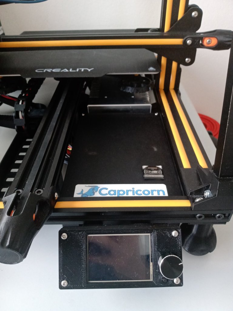
"The Last Stand" Mod As the name suggests, this is a stand alone mod for the Creality CR-10S, which allows the instalation of the BTT SKR v1.4 (turbo) board, a Pi4 (not included in this build) and the BTT TFT24 touch screen display. This mod includes only the items necessary for removing the control box. All other mods (uprights, tensioners, fan duckt) you can see on screen are not mine, but i can link them if there is enough interest. WARNING!!! THIS IS NOT A SIMPLE PROJECT! DISASSEMBLE YOUR PRINTER AT YOUR OWN RISK! I AM NOT RESPONSIBLE FOR ANY DAMAGE YOU, YOUR PROPERTY OR OTHER 3RD PARTY INDIVIDUALS MIGHT SUFFER WHILE UNDERTAKING THIS PROJECT! Ok, now that I have that out of the way, lets talk about the hardware needed before you stard actually printing. - Wire strippers - Soldering iron and solder - for some cable connections. - Multimeter - for checking everything for continuity. - Allen keys - Small screwdriver - for the board terminals. - Crimping pliars for your chosen connectors (JST / Dupont) - JST / Dupont connectors - both should work equally fine, it's down to personal preference. - Generic cable lugs - for the PSU connections (you need the fork connector in particular) - Button Head Nuts and Bolts set (from M2 to M5) - or to be more precice: * 6x M3x6 bolt * 4x M3x8 bolt * 16x M3x12 bolt * 30x M4x8 bolts ( 16 of these you can recycle from the original feet) * 4x M4x25 bolt (exhaust fan bolts; recycle old ones and/or included with new one) * 8x M5x8 bolt * 2x M3 hammer nut / extrusion nut * 25x M4 hammer nut * 8x M5 hammer nut DOUBLE CHECK FOLLOWING PARAMETERS: Needed cables for the project (stock 12V, 15A Power Supply Unit): - 14 AWG silicone insulated cable - for heated bed - 16 AWG silicone insulated cable - for the PSU connections - 18 AWG silicone insulated cable - Hot end heater - 22 AWG silicone insulated cable - all other logic connections ( steppers, endstops ...) 4x Squash balls You now will need to print out the parts needed for the project. Do not forget that you also need some cable clips for the frame (I didn't bother designing any because there is more than enough on this website). The display case is a 0 tolerance part, so if it doesn't fit your particular display, you should adjust your thermal expansion settings. You can mix and match colors as you like. I designed all of them so that they can be printed with minimal to no support. For the parts that have contact with heated elements ( PSU, MOSFET, Motherboard) I suggest using PETG. Standard 0.4 mm nozzle and 0.2 mm layer height should work just fine. (Optional: 0.6 mm nozzle and 0.4 mm layer height for faster printing at the minor expense of some quality). Now that you have everything gathered it's time to start the fun part: Step 1: Double check you actually have everything! ( Seriously, the last thing you want right now is to need a printed part with your printer disassembled). Step 2: Disconnect the power and let it sit for a couble of minutes. ( There is a big coil in the PSU which stores some residual power even if the cable isn't plugged in, ask me how I know...) Step 3: Take a picture with your phone for referance before you start tearing everything appart. Salvage the following items from your original control box: - Power Supply Unit (PSU) - Power Terminal ( where you plug the cable in) - On/Off switch - MOSFET (that small green board at the back with the huge heatsink) - exhaust fan ( if you don't have a new one) - case cooling fan ( again, if you don't have a new one) - 4 PIN female connector ( the one your heated bed plugged into) - 8 PIN female connector ( the one your hot end plugged into) - All motor/endstop cables ( label these to be sure, as you can easily confuse which end goes where) Step 4: Disassemble your printer untill it looks like the reference picture ( Image 1) Step 5: Mount the squash ball feet to the frame, then tilt it to one side. - 17x M4x8 bolts - 17x M4 hammer nuts (no point in putting the squash balls in right now, because they'll just fall off) Step 6: Screw in the power terminal and press in the on/off switch in their corresponding places on the leg. You can use the original cables that came with them to connect them later to the PSU. - 2x M3x8 bolt Step 7: Solder in new wires and extend the original ones of the 8 PIN connector. Be careful which cable goes where! (Image 3A / 3B) - Soldering iron and solder - 18 AWG cable - JST / Dupont connectors - Crimping pliars - Extension rough lenght: for connectors: 50-55 cm, for soldered wires: 60-65 cm (Measure to be sure!) Step 7A: Solder in new wires and extend the original ones of the 4 PIN connector. Again, be careful of what goes where. - 14 AWG cable for heated bed - Extension rough lenght: 50 - 55 cm (Measure to be sure!) Step 8: Screw in your 8 PIN connector to the bracket and then screw it in place below the z-Stepper motor. - 2x M4x8 bolt - 2x M4 hammer nut Step 8A: Screw in your 4 PIN connector to the bracket and then screw it in place at the back side of the printer, ideally right bellow where the heated bed cable comes out. - 2x M4x8 bolt - 2x M4 hammer nut You can now connect all your extension cables, but do not bind them together yet, as there are some other cables that you will need too. Step 9: Make extension cables for the X-Motor, Extruder and X-Endstop. - JST / Dupont connectors - Crimping pliars - Soldering iron Step 10: Start binding your cables together from the connectors onwards. - For the 8 PIN: From there you should have all the cables from the connector itself and the Z1-motor, Z-Endstop, X-motor, X-Endstop and Extruder ( all connectors should meet at the same point under the frame, as to give you a rough idea of how long to leave the cables before the connector. Keep seperate from the other looms. - For the 4 PIN: Same as above, but the positive power cable for the bed should be shorter and should deviate almost imediately after the central frame member. From that point you will need to bind in the Y-motor, Y-Endstop and Z2-motor cables to this loom. Make sure you leave enough room for the Z2 cables. Keep seperate from the other looms. Step 11: Mount the cable cover to the frame. Mount the PSU support clamps to the PSU, but do not bolt it in place for now. Now is the time to route the cable from the PSU to the new control box through the hole in the cover. The new cables should be 40-45 cm long. - 2x M4x8 - 2x M4 hammer nut Connect the cables to the PSU ( + power switch and power terminal). Mount the PSU to the frame and inside the cable cover. The mounts should sit flush with the cable cover. Route these wires seperately from the other 2 looms. Use Image 4 for reference. Step 12: CHECK ALL CONNECTIOS BEFORE GOING FURTHER! Seriously, use the multimeter to check that everything is in order. Imagine going through all this only to fry the motherboard, for example. Take your time with this step. - Multimeter Step 13: Take the middle part of the new control box and screw in the exhaust fan. Take the flat cables and mark them with a permanent marker (1 and 2). Place all display cables in their allocated slot in the part, then screw in the bottom plate ( where the motherboard sits). - 4x M4x25 bolt ( they cut their own thread so expect resistance) Step 14: Bolt the case to the frame. It should sit flush on 3 sides with a little bit of room between it and the PSU. - 4x M5x8 bolt - 4x M5 hammer nut Step 15: Bolt the MOSFET in its place and connect all necessary cables accordingly. (The largest hole in the case is meant for this). - 2x M3x6 bolt Step 16: Insert the cables from the 2 remaining looms through the 2 free holes in the box. ( I chose the PSU side hole to be Heated Bed and the exhaust fan side hole to be Hot End) Step 17: Connect the cables to the screw terminals on your motherboard before bolting it in place. Make sure you check everything with the corresponding official wiring diagram (not here!) - Small screwdriver Shorten cables and/or make connections as seen fit. Make sure all cables are under no strain. No cables should be touching the MOSFET Heatsink. Step 18: CHECK ALL YOUR CONNECTIONS! This should be the final check of everything you have done so far, really take your time and go over everything. - Multimeter Step 19: Screw in your case cooler fan to the top part of the case. Connect the fan to one of the free terminals and screw the cover in its place. - 4x M3x12 bolt Step 20: Mount the nuts into the case first then fit the display and mount the bracket behind it as shown. ( Image 8A / 8B) - 2x M3 nut - 4x M3x12 bolt - 2x M3x8 bolt - 2x M4 Hammer nut Step 21: Connect the cables to your display. If your are not sure wich of the cables you labeled earlier goes where, you can check the official wiring diagram from the producer. Mount your display on the frame. Step 22 (Optional): Tidy up your instalation: bind loose cables, use cable clips to optimise routing etc. ... Hopefully everything should turn on without a hitch and you will now have an upgraded CR-10S wich is virtually silent. Enjoy! PS: If there are some aspects of the build I missed and/or you find unclear, leave a comment. I will try to adress these as soon as possible.
With this file you will be able to print CR-10S "The Last Stand" Mod with your 3D printer. Click on the button and save the file on your computer to work, edit or customize your design. You can also find more 3D designs for printers on CR-10S "The Last Stand" Mod.