Tevo Little Monster filament detector and air temp sensor
thingiverse
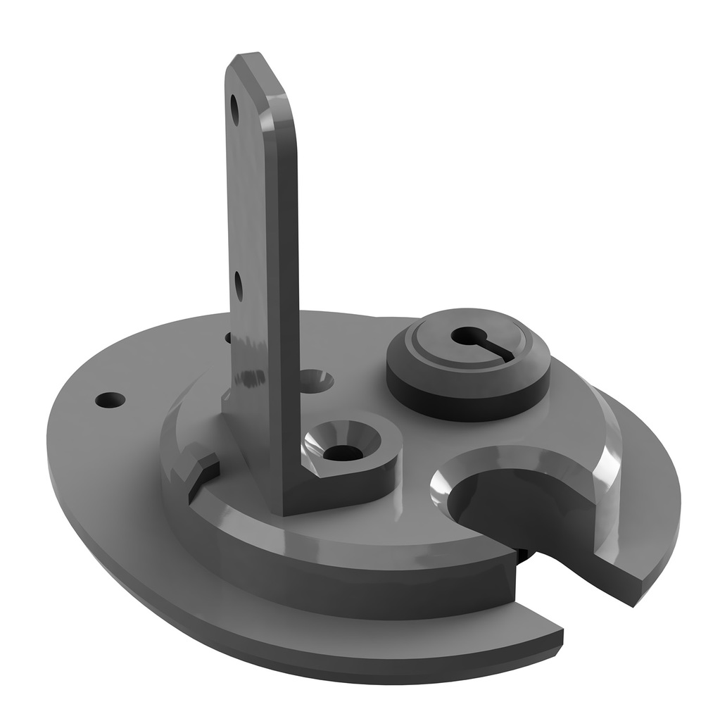
<h2>Description:</h2> This is a "stopple" for the 50 mm hole in the LM's top plate that fulfills three tasks: > Stuff the hole, so hot air is kept inside (if using a printer enclosure) > Integrate a swivel-mounted filament detector > Integrate a temp sensor to measure air temp inside the enclosure At first attempt I built bLITzJoN's LM filament detector, but (though it contains some really smart ideas) I was not fully satisfied with that solution: First, adjusting the microswitch was close to impossible due to the lever's too-long contact travel. Second, the switch's fixation is quite a loose fit, increasing the risk of unintended contact loss (and resulting "no filament" report and print pause). Third, the detector was neither usable with soft TPU filament nor bypassable. Well, since using TPU is, in my eyes, the sole reason to use a flying extruder, I decided to redesign the whole thing (and btw include an air temp sensor since the middle of the top plate is the perfect location for this). Still, I think it's just fair to give the remix kudos to bLITzJoN for the original idea without which I never would have made this thing. To avoid the microswitch issues, I decided to integrate a standard mechanical filament sensor. These cheap sensors are simple and reliable and also work with soft filament (to a degree). Yet there's the chance that some very soft TPU can't be pushed through the sensor, so I mounted the sensor to a lever. Thus it may simply be swivelled out of the way so it's bypassed by the filament. Optionally, a temp sensor to measure air temp can be attached (of course, this only makes sense if your Little Monster works in an enclosure). You can use virtually any digital thermometer with an external (cabled) sensor. While I was at it, I made five versions in total to offer maximum flexibility: <b>Cover plate full featured.stl</b> This is the cover plate having all the features described above. <b>Cover plate, Filasensor only.stl</b> This one lacks the temp sensor mount (which is useful only with a printer enclosure). <b>Cover plate, tempsensor and filament duct.stl</b> This one has the temp sensor mount and the filament duct, but no filament sensor. <b>Cover plate, no sensors.stl</b> This one features the filament duct only, no sensor mounts. <b>Cover plate, no holes.stl</b> This is a solid cover plate without any other purpose but "stuffing the hole" as an addition to an enclosure. <h2>How to print:</h2> Use whatever material you like for the plate and sensor lever. I used PETG which is quite a reliable choice for this purpose, but even standard PLA should have sufficient heat-proofness for printbed temps up to 150°C (which means about 45°C at the top plate). Please use at least 1.2 mm wall thickness and 40% infill to provide the needed degree of sturdiness. The temp sensor grommet and counter ring are intended to be printed using TPU but may also work if using some "harder" filament (though in this case it may be very hard to ever get the grommet out of the plate again). <h2>How to assemble:</h2> <b>Additional hardware needed:</b> Plate: To fix the plate you need two M3 x 10 mm flathead screws. Filament sensor - I used this one: https://www.amazon.de/gp/product/B07FSXFPLD/ref=ppx_yo_dt_b_asin_title_o01_s00?ie=UTF8&psc=1 This sensor type is offered from countless brands, nevertheless, the sensors are all the same. Just kepp an eye at the dimensions which should be the same as in my link above. Pricing starts at about three bucks (if ordering directly from China) up to about eight bucks. Aditionally, you will need two M3 x 20 mm screws and nuts and one M4 x 10 mm (or longer) screw with a countersunk head. Temp sensor: Any digital thermometer with a cabled sensor (or even an inflexible probe tube) will do the job. Further fixture material is not needed. <b>Mounting the plate:</b> The plate is inserted in the top plate's hole from underneath. First, grip the printer's cable harness (the ribbed hose) in the plate's slot, then press the plate into the top plate. Rotate it so that the two screwholes fit the threads in the top plate and then insert the two M3 x 10 mm screws. <b>Mounting the filament sensor:</b> Screw the lever to the plate using the M4 countersunk head screw. Do <b>not</b> re-tap the plate's screwhole since the screw should not turn too easily. Tighten the screw just enough to still be able to swivel the lever between the two stoppers on the plate. Next, screw the sensor to the lever in the orientation shown in the photos above. <b>Connecting the filament sensor:</b> This is a little special: These sensors are known to usually be cabled in the wrong order for most boards, so be sure to measure the contacts before you plug the cable to the board (using a multimeter or circuit checker). Expected behaviour is that two of the contacts make a closed circuit when there's filament inside the sensor while the third does not conduct anything when measured with either of the other two. In my case the logic board is a Duet 2 Wifi which supports simple short circuit switches without a polarity as sensors. So I just measured which two contacts closed the circuit when filament was inserted into the sensor. I crimped these two leads into a 3-pin Molex KK plug and plugged this into the E1 slot on the Duet like this: <img src=https://cdn.thingiverse.com/assets/d3/58/f0/23/be/featured_preview_duet_4250499.jpg> Note that only the red and black leads are connected to the board while the white lead is cropped (a little hard to see in the photo) since this is not needed for the "simple sensor" type. <b>Configuring your printer's firmware for the filament sensor:</b> Again, this is the instruction only for the Duet 2 (Wifi or Ethernet) board using Reprap V1.21+ firmware. I don't know how to handle this on other boards, especially the LM's stock MKS board using Teacup (earlier versions: Smoothie) firmware. If someone can figure this out, I would be happy to add the information. For the Duet, just open the config.g file and add the following commands anywhere above the M501 command: <b>; Filament Sensor config M591 D0 P2 C4 R20 S1 ; extruder drive 0 uses E1 endstop slot, switch mode NO, 20% tolerance M591 D0 ; display filament sensor parameters for extruder drive 0</b> In the (unlikely) case that your sensor switch's mode is NC (closed when there's <b>no</b> filament inside), the P parameter has to be changed, resulting in this command string: <b>; Filament Sensor config M591 D0 P1 C4 R20 S1 ; extruder drive 0 uses E1 endstop slot, switch mode NC, 20% tolerance M591 D0 ; display filament sensor parameters for extruder drive 0</b> What I can say about other boards (it isn't much, but maybe it's helpful for some users): Generally, the M591 command should work with any board using Reprap firmware, Version 1.21 and above (though, if using a board other than the Duet, you will most likely have to modify the C parameter to reflect the slot used). In return, with any G-code flavour other than Reprap, M591 is not supported, so you will have to find some information source (best find some printer-specific communities). Also a good info source is this: https://reprap.org/wiki/G-code <b>Mounting the temp sensor:</b> This is the easiest part: First slide the counter ring on the sensor's cable, then put the sensor into the printer through the 12 mm hole in the base plate. Fumble the sensor into the grommet and stick the grommet with the sensor into the 12 mm hole from underneath, then finally plug the counter ring on the grommet. Finished! <b>And what about filament bending?</b> There's one downside to guiding the filament through a tight duct: The filament is unavoidably bent while being spooled off. The range of bending angles results from the spool's width, the quantity of remaining filament on the spool, and the vertical position of the spool. Well - you can hardly affect the first and second of these aspects, but you can change the third (by simply mounting the spool holder somewhat higher). I designed a "lifted" spool holder base fitted to the Little Monster screwholes that you can download here on Thingiverse (https://www.thingiverse.com/thing:4840931), and recommend to use this or something similar. If you own a Little Monster you may want to keep an eye on my designs as I'm currently uploading parts for that printer successively. Also check 3Dvice's Little Monster parking brake: https://www.thingiverse.com/thing:2721009 This is one essential part no Little Monster should be without!
With this file you will be able to print Tevo Little Monster filament detector and air temp sensor with your 3D printer. Click on the button and save the file on your computer to work, edit or customize your design. You can also find more 3D designs for printers on Tevo Little Monster filament detector and air temp sensor.