TFT35-E3 case for Ender 5 Plus
prusaprinters
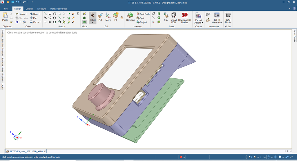
<p>Enclosure for <i>BigTreeTech TFT35-E3</i> dual-mode screen, for replacing the standard display on the <i>Ender 5 Plus</i>.</p><p><strong>Requires a total of nine M3 bolts, 8 mm minimum length</strong></p><ul><li> M3 × 8 mm (or longer - up to 12 mm) <strong>×7</strong> – four for holding the TFT35-E3 board between the Back and Front (ensure that the Button is placed before closing the case), and three for securing the Mount to the Back (install Mount inside E5 Plus case, where old display was located). </li><li>M3 × 8 mm (or longer - up to 20 mm) <strong>×2</strong> – for securing the Rear to the Back.</li></ul><p>Pre-thread the M3 bolts into parts to make final assembly easier.</p><p><strong>You will need to print the following</strong></p><ol><li><i>TFT35-E3_Front_rev4.stl</i></li><li>If no WiFi modue: <i>TFT35-E3_Back_rev4.stl</i>. If a WiFi modue installed:<i> TFT35-E3_Back_rev4_wifi.stl</i></li><li><i>TFT35-E3_Rear_rev4.stl</i></li><li><i>TFT35-E3_Mount_rev4.stl</i></li><li><i>TFT35-E3_Button_short.stl</i> or <i>TFT35-E3_Button_long.stl</i> (or <i>TFT35-E3_Button_short_larger.stl</i> or <i>TFT35-E3_Button_long_larger.stl</i> if a tighter fitting button is desired). *</li></ol><p>(* The long button protrudes above the top of the front of the case. As this is for resetting the display, I made a short version that does not protrude, making it more difficult to accidentally depress.)</p><p>Built in RS DesignSpark Mechanical, using the 'things' as mentioned in the remix section as inspiration and to check initial dimensions. Source files included for modifications.</p><p>Photos show components for my use, without the WiFi opton. If you have the WiFi module, then you can print the '<i>TFT35-E3_Back_rev3_wifi.stl</i>' variant. (Or customise from the DesignSpark Mechanical files).</p><p> </p><p><i><strong>Earlier Revision options (suggested to use Rev4 parts above)</strong></i></p><p>For these earlier revisons, screw-holes have been left in the corners of the <i>Back</i> and <i>Front</i>, but should not be required. The four screws that sandwich the TFT35-E3 between the <i>Back</i> and <i>Front</i> should be sufficient.</p><ol><li><i>TFT35-E3_Front_rev2.stl</i> (or <i>TFT35-E3_Front_rev3_cut.stl</i> or <i>TFT35-E3_Front_rev3_cut_low.stl</i> – see notes)</li><li>If no WiFi modue: <i>TFT35-E3_Back_rev3.stl</i> or <i>TFT35-E3_Back_rev3_410mm.stl</i>. If a WiFi modue installed: <i>TFT35-E3_Back_rev3_wifi.stl</i> or <i>TFT35-E3_Back_rev3_wifi_410mm.stl</i>.</li><li><i>TFT35-E3_Rear_rev2.stl</i> or <i>TFT35-E3_Rear_rev3_410mm.stl</i></li><li><i>TFT35-E3_Mount_rev2.stl</i> or <i>TFT35-E3_Mount_rev3_410mm.stl</i></li><li><strong>Buttons are unchanged: </strong><i>TFT35-E3_Button_short.stl</i> or <i>TFT35-E3_Button_long.stl</i> (or <i>TFT35-E3_Button_short_larger.stl</i> or <i>TFT35-E3_Button_long_larger.stl</i> if a tighter fitting button is desired).</li></ol><p><i>Note that the 'TFT35-E3_Rear_rev2.stl' component should be able to be modified for ports to bring through USB and card connections from the printer mainboard. This will be updated if I do so when the BigTreeTech SKR 1.4 is installed in my Ender 5 Plus.</i></p><h4><strong>Notes</strong></h4><ul><li><strong>Recommended parts have “rev4” present (except for the buttons). Alternatve parts (refer to “Earlier Revision Options” above) have "rev2" or "rev3" present. Earlier revisions were for testing only and were not uploaded.</strong></li><li>Feedback from one person was that they needed to use a 102% multiplier to obtain a correct fit as it was too tight for their board at 100%. Please print the 'TFT35-E3_Front_rev2.stl' first and check for a good fit. <i>[Note added 2020-10-08.]</i></li><li>Note from feedback on the screen location: the screen is secured with an adhesive pad, and may not be perfectly aligned with the front bezel. Test fit the board, and then — carefully — remove and shift the screen if required. The other option is to fit the board, measure how far the window must be moved, then open the source in DesignSparkMechanical and move the window. <i>[Note added 2021-02-08.]</i></li><li>Note from feedback on the button: there is now a "large" option for each height of button, which is 11.5 mm x 11.5 mm maximum, while the standard is 11 mm x 11 mm. (Based on the suggestion from one person of X 11.8 mm x Y 11.8 mm x Z 5.7 mm.) If it is still too small or loose, then upscale in the slicer or shim it with some soft rubber or similar. Important:ensure that it won’t stick when depressed: it must be a ‘click’ then return operation. <i>[Note added 2021-02-08. Updated 2021-10-15.]</i></li><li>Note from feedback on WiFi case: the WiFi module may have been too tight in the cutout for it. I don’t have this, so sized from the drawings. The part has been updated with additional clearance. <i>[Note added 2021-02-08. Updated 2021-10-15.]</i></li></ul><p> </p><h4><strong>Updates</strong></h4><p><strong>Updated 2020-08-12:</strong></p><p>Slight changes to STLs – mainly additional chamfers to aid with threading bolts.</p><p><strong>Updated 2020-08-14 (again):</strong></p><p>Photos of Rev2 parts included. Note TFT cable routing shown in last two photos, to avoid the screw boss. Changed minimum suggested bolt length for attaching Rear component to Back.</p><p><strong>Updated 2021-10-15 / 2021-10-16:</strong></p><p>• Added "TFT35-E3_Front_rev3_cut.stl" and "TFT35-E3_Front_rev3_cut_low.stl" with reduced front top height by 4 mm and 6 mm respectively. If your printer bed is making contact when lowered fullly then this is an alternative to reduce the height of the case slightly. (Note that if you want to use the corner screw holes the top two are now shallower.) [Slight modification to correct weird chamfering and addition of 'low' variant, 2021-10-16.]</p><p>• Added "large" button options.</p><p>• Updated "<i>TFT35-E3_Back_rev2_wifi.stl</i>" to "<i>TFT35-E3_Back_rev3_wifi.stl</i>", allowing an additional 0.25 mm of clearance for the WiFi module.</p><p><strong>Updated 2021-10-16:</strong></p><p>• Reviewed clearances and have created a "410mm" variant for the Back, Rear, and Mount parts. These will shift the display 3 mm lower down the front of the printer base, and should hopefully allow those using a 410 mm Z-height to just clear the display case.</p><p>• Removed the brace across the center of the Back part as this is unecessary and makes attaching cabling more difficult.</p><p><strong>Updated 2021-10-16 (again):</strong></p><p>Simplified Rev4 created that is 6 mm shorter and shifted down 3 mm as per the Rev3 '410mm' modifications – this redesign should prevent any contact with the bed if you have modified your Z-axis to 410 mm travel. Suggested to now use Rev4 uness you want to use the original corner screw holes (should not be necessary) or you are making spare parts for an earlier revision. Reduced height of aperture for screen by 1.5 mm.</p><p><strong>Updated 2021-10-17:</strong></p><p>Slight change to aperture for display. Reduced width on right side after printing and checking dimensions.</p><h3>Print Settings</h3><p><strong>Printer Brand:</strong></p><p>Creality</p><p><strong>Printer:</strong></p><p>Ender 3 Pro</p><p><strong>Rafts:</strong></p><p>No</p><p><strong>Supports:</strong></p><p>Yes</p><p><strong>Resolution:</strong></p><p>Adaptive 0.16 mm (in Cura 4.6)</p><p><strong>Infill:</strong></p><p>20%</p><p><strong>Filament:</strong> Hobby King Premium PLA-X</p><p>To suit</p><p><strong>Notes:</strong></p><p>Supports only where needed. Suggested to use 'from build plate' for <i>Back</i> and <i>Mount</i> parts only.</p><p>Category: 3D Printer Parts</p>
With this file you will be able to print TFT35-E3 case for Ender 5 Plus with your 3D printer. Click on the button and save the file on your computer to work, edit or customize your design. You can also find more 3D designs for printers on TFT35-E3 case for Ender 5 Plus.