The Anti-Gravitator Thru-Hole Version
thingiverse
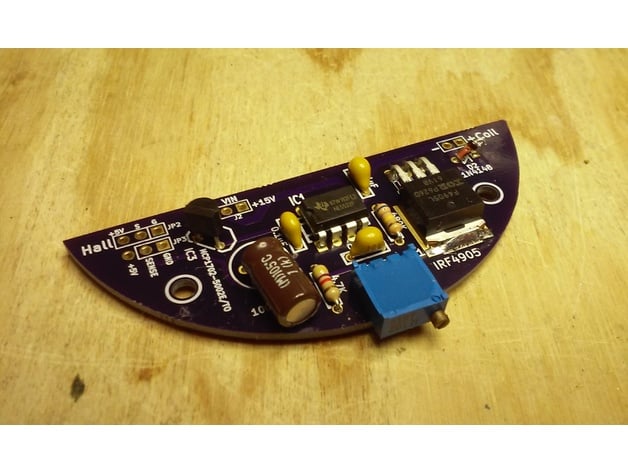
I started work on building the Anti-Gravitator and didn't like the price of the original board on OSHPark. Most of the board was unused space, so I fired up KiCAD and reworked it into a much more price-effective board to run on OSHPark: https://www.oshpark.com/shared_projects/7TnLB2hD. While I was reworking it, I decided to go all through-hole on the parts to make it quicker to solder together. Plus, I have more through-hole parts on-hand than surface mount anyway. It's designed to fit in the original Anti-Gravitator base, but only occupies part of the space and only needs two mounting holes/screws to attach. All of the KiCAD design files are in the posted zip-file and since it's already posted on OSHPark, you can order it with a few clicks. Update (13-Jan-2017): I've removed the "Work in Progress" tag, as I've gotten my boards in and have assembled one and it works perfectly! No issues with the board at all, and it fits perfectly in the base. The only issue I had during assembly was that I got the polarity of the coil backwards initially. There's a 50/50 chance you'll get it right, which means it's a 99% chance I'll get it wrong (Murphy's Law). If you are setting it up for the first time and you find that as you adjust it, it doesn't seem to be doing anything, and there's a single point in the adjustment band where it wants to slightly repel the magnet instead of attract it, you most likely need to switch the wires to the coil and reverse its polarity. When you have the polarity correct, you'll feel the magnet start to vibrate in your hands as you hold it in place and adjust the potentiometer and get near the "resonance point". If you don't feel it vibrate anywhere within the adjustment range of the potentiometer, you most likely need to switch the leads to the coil. The through-hole parts I used are: 1 - MCP1702-5002E 5V, 250mA LDO TO-92 Voltage Regulator (DigiKey: MCP1702-5002E/TO-ND) 1 - NE5532P OpAmp (DigiKey: 296-1410-5-ND) 1 - P-Channel 55V 42A MOSFET (DigiKey: IRF4905LPBF-ND) 1 - 4.7k ohm 5% 1/4W resistor 1 - 680k ohm 5% 1/4W resistor 3 - 0.1uF ceramic disc capacitor (5.08mm/0.200" lead spacing) 1 - 100uF 25V electrolytic capacitor 1 - 1N4148 diode 1 - 1K multiturn Bourns 3299W potentiometer (or equivalent) 1 - A1302 Allegro Ratiometric Hall-Effect (DigiKey: 620-1022-ND). Note: Allegro has end-of-life'd this Hall-Effect sensor. As of this posting, DigiKey still has over 11,000 of them. But I don't know what Hall-Effect will be a suitable replacement should they run out. So you may want to check its availability first and/or find a replacement before starting this build. For the coil, I used 30ga magnet wire and wound enough to fill the spool (I didn't measure the length, but I've included a picture of my wound coil). When complete, it measured 50.8-ohms. The power adapter I used was a Cabletron Systems 120VAC 60Hz 19W Power Adapter off Amazon, since it was only $5(USD). Though rated at 15VDC at 900mA, it actually measured between 19-20VDC when not under load (I didn't bother measuring it with a load). I just cut the connector off and soldered the leads to the board. On the one I received, the lead with the stripe was the positive lead, but be sure to check yours with a volt meter before attaching the leads to the board, since reversing the power supply polarity could damage it.
With this file you will be able to print The Anti-Gravitator Thru-Hole Version with your 3D printer. Click on the button and save the file on your computer to work, edit or customize your design. You can also find more 3D designs for printers on The Anti-Gravitator Thru-Hole Version.