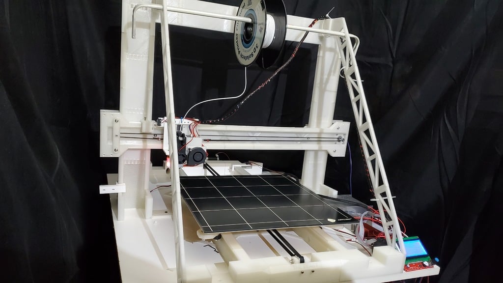
THE BEAST - FULLY 3D PRINTED FRAME AND RAILS 3D PRINTER
thingiverse
This text appears to be a detailed list of parts required to build a 3D printer, specifically a printer called "Cyclops" or "Chimera". The list includes various components such as frames, rails, stabilizers, extruder mounts, and more. Here are some specific details that can be extracted from the text: 1. The printer has a top frame with several parts: Main Top Center, Main Top Inter, Main Top Left, and Main Top Right. 2. The Z-axis rail consists of two parts: Z Rail 35 (for the inside) and Z Rail 112 (for the outside). There are also 12 Z Axis rails that slide onto the frame. 3. Optional components include an Optical Z Mount and a BL Touch mount. 4. The stabilizer system includes several parts such as Pin to Y Front, Stabilizer Lower, Middle, Upper, and Pin. 5. The extruder mount consists of multiple parts including Extruder Bracket, Fan Bracket, Mounting Plate, Tensioner 1 and 2, BL Touch mount (optional), X Limit Switch mount with or without BL Touch. The text also includes updates on the design, mentioning that it is 99% complete and only needs a box for the power supply and control board. It also mentions that the second attempt at Cyclops has been successful and some new files have been added to the list.
With this file you will be able to print THE BEAST - FULLY 3D PRINTED FRAME AND RAILS 3D PRINTER with your 3D printer. Click on the button and save the file on your computer to work, edit or customize your design. You can also find more 3D designs for printers on THE BEAST - FULLY 3D PRINTED FRAME AND RAILS 3D PRINTER.