The FIBIAC - a simple electromechanical computer
thingiverse
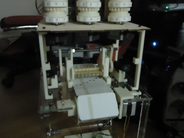
Build a simple electromechanical computer using punch cards by following these steps: 1. Print and assemble three 3-digit counter registers and arrange them artistically on a sheet of plywood. 2. Use a laser cutter to cut out the necessary frames for the punch-card reader. 3. Assemble the punch-card reader by attaching a copper-clad board with spring-loaded pogo pins, protoboard, and hol plate holder. 4. Mount a servo cam onto a hobby servo and attach it to a threaded rod. Repeat for the other side. 5. Attach a NEMA17 stepper motor to a motor mount. 6. Laser cut two copies of 'instr_card_box.dxf' out of plywood or acrylic and glue them together. 7. Attach axle stoppers to the instr_card_box assembly. 8. Connect four stepper motor drivers to control the four stepper motors (three for counter registers, one for card advance). 9. Solder wires to the copper plate beneath the pin array and connect them to the ground plate and zero detect plate. 10. Control the counter registers by connecting their enable and direction signals to the stepper drivers. Optionally, connect a buzzer or lamp to an alert signal. 11. Connect the zero_detect pins from each register to the zero_detect plate through a series of reed switches. 12. Program your microcontroller with an algorithm that lowers and raises the pin array, reads the zero_detect signal, rotates the enabled counter registers, advances the card chain, and raises the pin array again. 13. Print out instruction cards using a hole punch and overlay them with a template. Tape the cards together to form a circular chain. 14. Position the instruction chain under the pin array and manually lower it for alignment. 15. Power up your machine and enjoy watching it compute!
With this file you will be able to print The FIBIAC - a simple electromechanical computer with your 3D printer. Click on the button and save the file on your computer to work, edit or customize your design. You can also find more 3D designs for printers on The FIBIAC - a simple electromechanical computer.