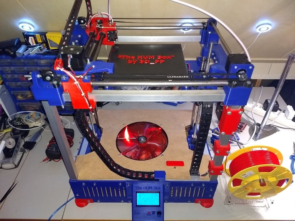
"The HUM Box V1" Completed (Working Prototype) and (Sneak Preview "The HUM Box V2.0" Final)
thingiverse
This is the build guide for the 3D PP printer model 2. The text outlines all the parts needed and their quantity for assembly. It also provides notes on building the frame, alignment of Z-Axis supports, tips for printing the heatbed brackets, and safety warnings when starting to print. Here are some key points extracted from this guide: ### Parts Needed * **Frame:** * 20 x 20 Corner Bracing (3 way 90 degrees) - 8 times * Frame extender - 4 times * Foot - 4 times * **Print Bed:** * Mk2 Heat Bed Bracket - 4 times * 20 x 20 End Cap - 4 times * **Z-Axis Supports:** * Z-Axis Support Bottom (116mm) - 2 times * Z-Axis Support Top (116mm) - 2 times ### Other Parts: * X-Axis Bracket Front * X-Axis Bracket Front clamp * X-Axis Bracket Front motor * X-Axis Bracket Front motor clamp * X-Axis Bracket Back * X-Axis Bracket Back clamp * X-Axis Guide bracket * X-Axis Guide bracket clamp * Y-Axis Motor Bridge * Z_MIN switch holder * Bracket clamp - 3 times * Motor bracket clamp * Belt Tensioner - 3 times ### Safety Precautions: * Do not forget to switch on cooling when printing, or you will end up with a clogged extruder/overheated board. * Building this printer is at your own risk. Always shut down the main voltage input when working on electronic components.
With this file you will be able to print "The HUM Box V1" Completed (Working Prototype) and (Sneak Preview "The HUM Box V2.0" Final) with your 3D printer. Click on the button and save the file on your computer to work, edit or customize your design. You can also find more 3D designs for printers on "The HUM Box V1" Completed (Working Prototype) and (Sneak Preview "The HUM Box V2.0" Final).