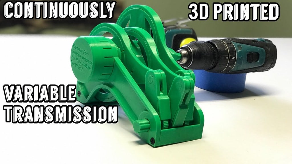
The Ratcheting CVT
thingiverse
Description: https://youtu.be/G9-N-nIqc4g Assembly: https://youtu.be/2hdSGDdjpeQ #####Torque Capabilities Please know that i designed this CVT for a demonstration model, it's not intended to be used as an actual transmission ####How This Works - Watch the video! ##### Hardware Required! - 2 Sheetrock screws 1" or 2" long. - 4.5mm BB's <a target="_blank" href="https://www.amazon.com/gp/product/B00419J4X0/ref=as_li_tl?ie=UTF8&camp=1789&creative=9325&creativeASIN=B00419J4X0&linkCode=as2&tag=geardownforwh-20&linkId=c9418267083c5464be015db05e4c7b0e">You Need These BB's</a><img src="//ir-na.amazon-adsystem.com/e/ir?t=geardownforwh-20&l=am2&o=1&a=B00419J4X0" width="1" height="1" border="0" alt="" style="border:none !important; margin:0px !important;" /> ##### Print settings - You need to calibrate your printer to +/- .02 mm on a 20mm calibration cube before you print this or it will not fit and/or work properly, use horizontal expansion to accomplish this if necessary, but often oversized parts are caused by printing speed or worn out nozzle. - It is also necessary to level your bed - especially if you have an auto leveling sensor. This one cause me to have to reprint due to compensation that is done after auto leveling. - 1.2mm wall thickness and 10% - 30% infill at .2mm layer height. - Print everything in the orientation that it's already in (yes print the cam adjustment shaft horizontally) - Use supports where necessary, I think I marked everything that needs it but use your own judgement. - PRINT ALL THE GEARS (including the ratchet gear) together as a batch, but separate from all the other parts and slow your printing speed down substantially, otherwise they will come out too rough and will not fit together. ##### Part Preparation - Use a screwdriver (or the cam control shaft) to break the custom support material out of the inside hole of the crankshaft, this is there to help bridging and is only one(or two) layers thick. - Separate the eccentric components from each other, they should not be attached. - The two halves of the eccentric mount have a bearing race around them, its likely that the bearing race might have a small "bump" where the two halves meet due to printing jerk, use an exacto knife to make this bearing race nice and even. ##### Assembly - I plan to make an assembly video sometime, but until then, follow these instructions. - Assembly order 1. Assemble all three ratchets onto the output shaft, making sure that the ratchet pawl's are facing the clicker thingy, and the ratchet body's are facing the same way. 2. Install the crankshaft into the frame. The hex side of the crankshaft should be on the frame left side, then loosely place the three large pushrods (the giant circles) around the crankshaft. 3. Slide the output shaft with the ratchets into the frame. 4. Place the other side of the frame onto the machine, and use sheetrock screws to attach it. 5. Assemble the ratio adjuster gearbox, it's really hard to put together, and if it doesn't spin super freely you will need to reprint with a negative horizontal expansion setting. Ring gears need to be installed so that they are in the order of 1,2 6. Install the ratio adjuster with large carrier facing towards the frame, align the index marks on the crankshaft and the ring gear, and make sure the small carrier is facing out. 7. Install the cam control shaft through the entire apparatus, placing the cam gears into each pocket of the crankshaft in order of the marks on them with the marks facing the same direction, rotate the cam control shaft or the cam gears until the shaft slides through them( align the index position marks) 8. Install the ratio adjustment cover, aligning the notches on the cover to the notches on the ring gear. 9. At this point, the crank shaft should spin somewhat freely, and the cam gears should rotate at the same speed as the crankshaft assembly, if It does not, the gears are binding somewhere. 10. Install the two half's of the eccentric mount on the crankshaft in whichever spot you like, making sure to mate the rack of gears up with the cam gear. 11. Slide the pushrod over the top of the two halves of the eccentric mount and fill the grove up with 4.5mm BB's. 12. Once the raceway is filled with BB's, remove one or two BB's and then install the small wedge shaped piece into the bearing fill hole, the side with two faces should face out. I used a dab of hot glue to hold this piece in. 13. Repeat steps 8,9 and 10 for the other two eccentric's making sure not to flip them around (I.E. The build plate side should be on the same side for all three) 14. Place the wrist pins through the ratchets one at a time, use the eccentric offset adjustment to make the middle ratchet accessible #### Other Important Info: #####CAD Files?? - I Included the Fusion 360 Project with this, But the most recent version of this project can be downloaded in lots of different formats from this link: http://a360.co/2IhRLLa - Feel free to create your own modifications and parts for this project, and if you do, make sure you create a remix and upload them, I'll link to them and possible create a collection for all of them! #####Show Your Work! - Make a "make" and show everyone what you made! Everyone will thank you for it! ####For More Cool Gearbox Projects, Don't forget Subscribe to Gear Down For What?! https://www.youtube.com/c/GearDownForWhat #### Thanks! We are a participant in the Amazon Services LLC Associates Program, an affiliate advertising program designed to provide a means for us to earn fees by linking to Amazon.com and affiliated sites.
With this file you will be able to print The Ratcheting CVT with your 3D printer. Click on the button and save the file on your computer to work, edit or customize your design. You can also find more 3D designs for printers on The Ratcheting CVT.