TheUltiPad - a 23 Key Number Pad/Macropad with Rotary Encoder
prusaprinters
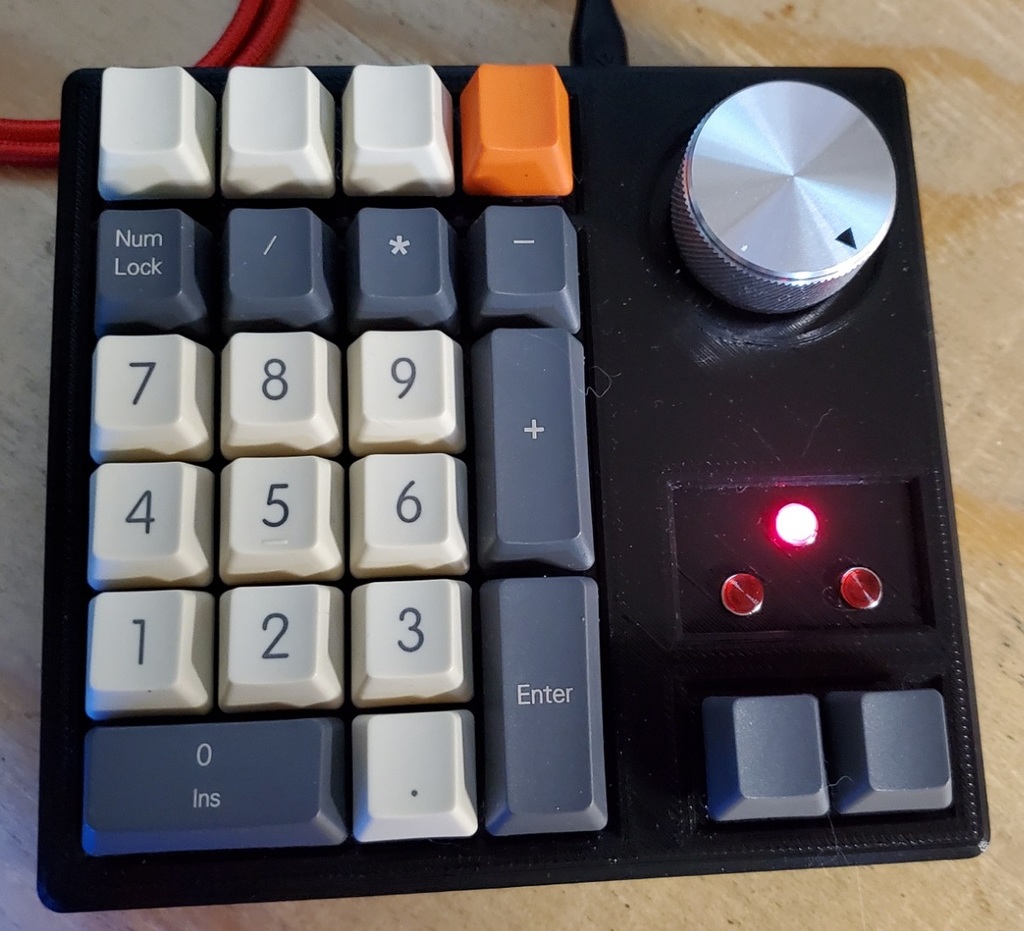
<p>I really liked the <a href="https://www.thingiverse.com/thing:4175635">dumbpad designs</a> i made earlier when i was using my full 104 key keyboard, but recently switched to a Drop CTRL tenkeyless as my daily-driver....and i found that i missed the numberpad functionality for a few specific daily tasks</p> <p>So i designed a numberpad, that also had all the functionality as the macropad app launcher - with the rotary encoder.....</p> <p>Therefore---TheUltiPad was born! (something, something, unimaginative name)</p> <p>Shown next to the CTRL for size comparison - its a little taller than i wanted, but had to add some height to account for the pro-micro along with the hand-wired switches, rotary encoder and LEDs.</p> <p>I will be uploading the raw QMK firmware folder and my hex shortly, I'm not yet in a position to fork and commit the files, but it forks well and is derived from the dumbpad firmware.</p> <p>The LEDs display Num-Lock at the top of the three, and Layer indicators above each of the layer switches - they are setup as TT() keys so they are both momentary and toggling.</p> <p>Parts List:</p> <ol> <li>23x Cherry MX switches of your choice (i use some Cherry blacks that i had)</li> <li>If you choose Costar or Cherry MX Stabilizers (i removed the Alps Stabs topas the bar collided with the switches, and i am using it fine without stabilizers)</li> <li>the really nice mxuteuk 35mm machined aluminum knob from Amazon</li> <li>3x 5mm LEDs (and appropriate resistors) i used <a href="https://www.radioshack.com/products/12v-led-assembly-with-6mm-holder-red?variant=20332063173">these from radio shack</a> -radio shack PN: 2760084</li> <li>Diodes: In4148 - you can get a cheap 100 pack from <a href="https://www.amazon.com?linkCode=ll2&tag=thingiverse09-20&linkId=e4759bff1fa9a55a0f897d801ce2d765&language=en_US&ref_=as_li_ss_tl">Amazon</a></li> <li>EC11 Rotary Encoder: Here is a 10 pack of EC11's from <a href="https://www.amazon.com?linkCode=ll2&tag=thingiverse09-20&linkId=e4759bff1fa9a55a0f897d801ce2d765&language=en_US&ref_=as_li_ss_tl">Amazon</a></li> <li>Pro Micro: 3-pack from <a href="https://www.amazon.com?linkCode=ll2&tag=thingiverse09-20&linkId=e4759bff1fa9a55a0f897d801ce2d765&language=en_US&ref_=as_li_ss_tl">Amazon</a></li> <li>Any USB Type B Micro cable for the Pro Micro</li> <li>4x M4x12mm socket head machine screws</li> <li>Various wire, soldier, etc. etc.</li> </ol> <p>Firmware notes:</p> <ol> <li>UltiPad.hex (precomiled firmware)</li> <li>UltiPad.zip (firmware folder for QMK build env.)</li> </ol> <p>If you want to use the compiled hex:</p> <ol> <li>The Keypad is the numpad as labeled</li> <li>The 4 top keys as PREV, PLAY, NEXT, STOP.</li> <li>The rotary encoder is Volume Up and Down, with the button as MUTE.</li> <li>The two bottom keys are setup as TT(1) and TT(2) (both a momentary and a toggle with double tap)</li> </ol> <p>a. Layer 1 sets all the numbered keys (0-9) as LCAG(1), LCAG(2), etc. and i use autohotkey as an app launcher for LeftCtrl, Alt, Win + a number</p> <p>b. Layer 2 sets all the numbered keys (0-9) as LCAG(A), LCAG(B), etc. and i use autohotkey as an app launcher for LeftCtrl, Alt, Win + a letter (a through j)</p> <p>Unzip the UltiPad.zip into your QMK folder in your build env, and modify/compile your own keymap.</p> <p>Let me know how you make out!</p> <p>Edit, added a slightly shortened bottom half (by 3mm) its the bare minimum to fit my internal parts.</p> <p>My other stuff (mostly Keyboards) <a href="/revere521/designs">https://www.thingiverse.com/revere521/designs</a></p> <h3>Print Settings</h3> <p><strong>Printer Brand:</strong></p> <p>Monoprice</p> <p><strong>Printer:</strong></p> <p>Maker Select</p> <p><strong>Rafts:</strong></p> <p>No</p> <p><strong>Supports:</strong></p> <p>Yes</p> <p><strong>Resolution:</strong></p> <p>0.2 mm</p> <p><strong>Infill:</strong></p> <p>20%</p> <p><strong>Filament:</strong> Hatchbox PLA</p> <p>Black</p> <p><strong>Notes:</strong></p> <p>Supports for the bottom (for the screw holes if your printer doesn't bridge well) and for the Cherry/Costar Stabilizer Top (for the switch opening overhangs)</p> <h3>Post-Printing</h3> <p><strong>THIS IS REVERSED SO IT MATCHES WHAT YOU SEE WHEN LOOKING AT THE BOTTOM OF THE TOP PLATE</strong></p> <p><strong>Hand-wiring Help</strong></p> <p>Wiring help - this is my best effort to match the wiring to the firmware and what I did on my prototypes - please proceed with care, i did my best with the diagram but offer no hard guarantees that i didn't mix up any pins here (just a disclaimer)</p> <p>First wire the array on the backs of the switches - columns of wires and rows of diodes following the black and red paths in the "Wiring" image, and the blue and green paths in the diagram.</p> <p>Here is a good hand-wiring guide to see the concept for the switch array: <a href="https://deskthority.net/viewtopic.php?t=6050">https://deskthority.net/viewtopic.php?t=6050</a></p> <p>For the Rotary encoder, the "2 pin side" is the push button for mute, the "3 pin side" is for the actual rotary encoder (left and right turning)</p> <p>I installed mine so that the 2 pins face the lower edge - so that its a straight shot from the pin to the switch below for the column; since the button function of the encoder is treated like one of the key switches in the array.</p> <p>Notice that column 5 is just the one Fn switch (the whole column is just the one pin on the switch), and column 4 is 1 switch and the one of the pins on the 2 pin side of the rotary encoder. The other pin on the "2 pin side" of the encoder is part of the diode row 1</p> <p>You need to solder a wire to the end of each diode row to the corresponding pin on the pro micro; and one from the end of each column to the corresponding pin as well - that creates your switch array</p> <p>In the zip file for the firmware - config.h calls out the row and column pins (and all the other pins in use)</p> <p>These are the rows 0 to 5 -></p> <p>define MATRIX_ROW_PINS { D7, E6, B4, B5, F4, F5 }</p> <p>These are the columns 0 to 5 -> notice that the order of the columns is physically reversed when soldering from the bottom of the plate, because it is upside down.</p> <p>define MATRIX_COL_PINS { D3, D2, D1, D0, D4, C6 }</p> <p>The Wiring Diagram are shown reversed to make it a little easier to look at - meaning its how it looks from the bottom when you are soldering so it should be:</p> <p>Rows top to bottom are 0 - 5; so row 0 would be pin D7; row 1 would be E6, etc.</p> <p>Then the Columns are left to right -> 5 to 0 when looking at the bottom/soldering side of the plate; so Column 5 would be C6; Column 4 would be D4; etc.</p> <p>the ground of the encoder (center pin on the 3 pin side) is wired to the GND on the pro micro (along with the negative/cathodes of the 3 LEDs)</p> <p>The pin on the "volume up side" of the encoder goes to the pro micro pin F6</p> <p>The pin on the "volume down side" of the encoder goes to the pro micro pin F7</p> <p>The LEDs may each need a resistor on the anode/positive side depending on your choice. Remember that raw voltage through the pro micro is 5v max, the LEDs i chose were 12 volt, so they did not need a resistor.</p> <p>The single NumLock LED - the anode/positive then goes to the pro micro pin B3</p> <p>The 2 lower LEDs for layer indication - the anode/positive legs are connected to pin B2 and B6 (when looking at the bottom/solder side of the plate) - the Left one goes to B2 and the Right goes to B6</p> Category: Computer
With this file you will be able to print TheUltiPad - a 23 Key Number Pad/Macropad with Rotary Encoder with your 3D printer. Click on the button and save the file on your computer to work, edit or customize your design. You can also find more 3D designs for printers on TheUltiPad - a 23 Key Number Pad/Macropad with Rotary Encoder.