Throttle Quadrant
thingiverse
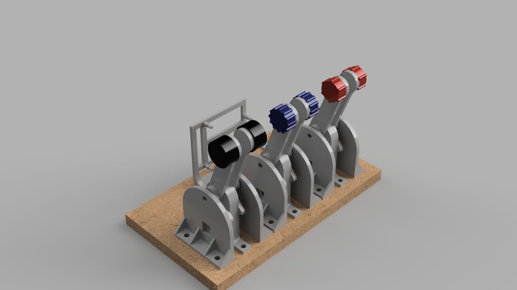
[NOTE: It appears many of the parts haven't been rendered in the preview] This includes some parts for a DIY throttle quadrant for your PC. I designed it mainly with Flight Simulation in mind, but it could equally be used for other applications. Levers can either be attached individually or doubled up per the photo. The lever is the only part that needs to be mirrored if using a twin lever setup. I've included the mirrored STL for that. I've included two types of levels. One has a 60 degree throw, and the other has 120 degrees. Either works fine, but needs to be matched to the corresponding gear. This design uses 10k LINEAR (logarithmic will not work properly) potentiometers. I'm using Jaycar part RP8510. Each gear is attached to a potentiometer which is in turn connected to an Arduino Leonardo. I've included the Arduino file which identifies which pins are allocated to which functions. The Arduino will then appear as another game controller in Windows (unsure if it will work on Mac or Linux, but assume it would). Each axis is provided with 10-bit resolution. I've included 2 different Arduino mounts, one horizontal and one vertical. Pick whichever suits your application. I like the vertical one as it saves a bit of space. I've also included a switch bracket if you want to add a switch to the Arduino. I use that to switch my racing pedals between normal mode (ie clutch/brake/accelerator) and flight mode (rudder/differential braking). The code shows how that works. All mounting hardware is M4. The base plates are 3mm thick, so you'll need to work out the appropriate length for your application. Each piece has 2 mounting holes. The lever screws are M4x50mm in a dual setup, but would be M4x40mm in a single lever setup. The levers are padded with M4 flat washers to the appropriate width. The knobs are interchangeable, so just glue in the appropriate one. Up to 6 levers are available in the standard program attached. If you're not intending on using pedals through the Arduino, then you can update the program and have access to an additional 3 levers. [Update 19 Aug 20] I've now been able to test 2 levers into the Arduino. I found a number of issues with the code, so I've uploaded a new version that should now work. I was trying to limit the joystick to just the axis provided, however that didn't appear to work. Now you'll see lots of switches that aren't connected. Axis inputs that are not connected appear to float with one of the connected inputs. This should only be an issue if those axis have been assigned in the game. Wiring up all inputs should alleviate the issue. [Update 22 Aug 20] I've completed building it and can confirm the code from 19 Aug 20 operates correctly with respect to the levers. The fit of the potentiometers is very tight, but everything else worked fine. I'm yet to test the racing pedal connection. [Update 23 Aug 20] I've updated the Main.stl to have a slightly larger diameter for the potentiometer thread. I found the fit was tighter than it should be. I also accidentally fitted logarithmic potentiometers. Due to the mirorring in the design, the pairs will not operate the same if using log pots. Left hand levers are generally ok (fine control at the top of the range and then it drops off rapidly), but right levers are the opposite. I've also made changes to the code as the pedal interface didn't work. It will now show up as two devices, one for the pedals and one for the throttles. Flight Sim 2020 also uses a button to activate thrust reversers, so I've added an input for that on pin 12. [Update 31 Aug 20] I've updated the Arduino code to enable a calibration mode. This assumes you're using the mode switch. Upon startup, moving the switch within 5 seconds will enable Calibration mode. The LED will flash during the 5 second window in which you can enable the mode. Once enabled, move all controls through their full range and toggle the switch when done. The values aren't saved at this stage, so if you reset the Arduino, the values will be lost. I've also added another 2 switch outputs to use as left and right brakes. FS2020 has a conflict that currently doesn't allow the left and right brake axes to be used without causing lever functions to also occur. Instead, simply map button 2 to left brake and button 3 to right brake and you'll get differential braking. You can adjust the brake resolution in the code. There's also a third button which I use to enable/disable thrust reversers. I use a push on/push off switch with LED for this. The LED output will light up the switch when the button is pressed. I've also tidied up the code so hopefully it's easier to follow. [Update 5 Sep 20] Inspired by alrubino's derivative, I've created some covers. These provide a low end stop to help protect the potentiometers. As a result, the levers may not work properly without calibration. These are designed to fit after the rest is assembled and are simply glued in place. I still need to figure out a way to create a high end stop. I've removed the 60 degree travel levers and gear now as I can't see them being useful, and because the cover is designed for the 120 degree levers. [Update 6 Sep 20] I've added a second Arduino file (multi_axis_v2.ino). This adds some functionality and also increases the number of connections available to the Arduino. This is very similar to the first but with 4 differences: 1) The mode switch has been removed and remapped to the thrust reverser switch 2) The mode switch is only read on startup and not all the time 3) The calibration table is now saved so you won't need to recalibrate every time you connect the Arduino. 4) When using the pedals in racing mode, the calibration values are now applied. Therefore, regardless of mode, when calibrating, use all 3 pedals. In the next update I'll remove the LED output for the thrust reverser button as it should be able to be wired outside of the Arduino to have the same function. That'll add another pin for additional switches. [Update 14 Sep 20] I've updated the multi_axis_v2.ino file to include a trim switch function. I've also moved more of the code into different functions. There's now a 'debug' option to enable the serial monitor function of the Arduino software. It currently reports the positioning of the 6 levers (0-1023). Just remove the comment from line 1 to enable it. I've found it does make it less reliable in starting up. I've also included a zero throttle constant that will ensure the throttles read 0 as I believe this helps with activating thrust reversers in FS2020. I was unable to remove the reverser LED function, so that's still there. There's now a new reverser bracket which includes a mount for the trim switch. To go with that is a paddle to attach to the mom-off-mom switch (Jaycar part ST0358). The reverser switch is Jaycar part SP0704.
With this file you will be able to print Throttle Quadrant with your 3D printer. Click on the button and save the file on your computer to work, edit or customize your design. You can also find more 3D designs for printers on Throttle Quadrant.