Throttle Quadrant for Flight Simulator
thingiverse
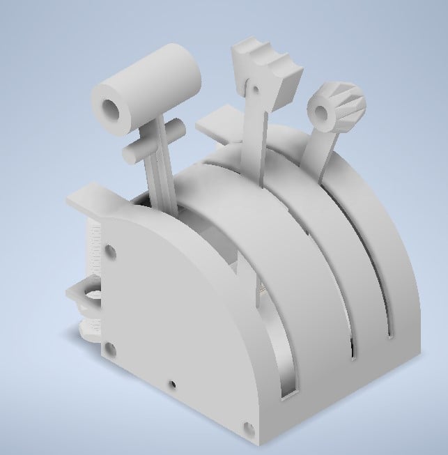
# Throttle Quadrant with Reverse Thrust for Flight Simulator ### Inspired on Cessna Caravan - One truly amazing aircraft! This throttle quadrant uses three analog ports in an Arduino to handle throttle, propeller and cutoff/mixture. It is fully compatible with the new Microsoft Flight Simulator 2020. The reverse thrust is toggled as a "virtual" button when the potentiometer reaches a threshold. This project uses two screws and nuts from Nut Job so we can attach the quadrant to the edge of a table. The Arduino I used for this project is the Arduino Pro Micro with **ATmega32U4** chip <ins>**(very important!!)**</ins>. This chip allows us to use the "Joystick" library (see code below) as it already has a USB HID feature. If you want to use an Arduino Uno or other that uses the **ATmega328P** chip the code below <ins>**won't work**</ins>, but it's possible to adapt it with minimal changes, please refer to the UnoJoy library and its examples: https://code.google.com/archive/p/unojoy/ ### Extra Materials Needed (that are not printed): - 9 screws for base case > *- The screws I used were 3.5 mm self-tapping that I had spare at home, you may need to tweak the holes to use a different screw.* - 3 screws to attach each top to the corresponding lever > *- These were also designed for the same screws as above (3.5 mm self-tapping). You may need to tweak the holes to use a different screw* - 1 ballpen spring; *(for the reverse actuator)* - 3 B10K potentiometers >*The potentiometers attach to the case using the nut provided with them (M6?). Do not use a washer.* - Arduino with **ATmega32U4** chip (Pro Micro, Leonardo, etc.) - Wires/Soldering Iron/DuPont Pins ### How to Print: - The case parts are designed to use support only on the potentiometer stand and table attachment holes. For both of these a standard "tree" support from Cura will work. > *- For Cases 1 and 4 make sure you print them on their side with the solid face down* > *- For Cases 2 and 3 make sure you print them on their side it with the lever slot facing up.* > *- If you see supports other than the ones I mentioned, you're probably using wrong orientation.* - Print all the lever sideways. >*- The throttle lever needs a support on the potentiometer hole* >*- The propeller lever needs a support on half of it's extension so you can print the bended portion, make sure that bend is facing up* >*- The cutoff/mixture lever also needs a support on half of it's extension for the bended portion, make sure the bend is facing up* >*- The reverse lever is printed with the handle (large cylinder) facing up, you'll need TWO of these for our Throttle Quadrant. You'll need a support on almost all the extension. You might want to use a "brim" for this one.* - The bolt and nut are printed vertically - This is important so the thread works! - You'll need two of each. ### Assembly: I honestly didn't give that part a lot of thought so it might be a little tricky with all the wires soldered...my bad, but it is possible and it works. 1) Solder all wires to the potentiometers, make sure you take their orientation into account (the cutoff/mixture pot is facing the opposite way). 2) Get the wires thru the hole on Case 1. 3) Attach the pots to their stand using the nut that came with them. Pay attention to the orientation. 4) Attach each lever to their corresponding top using the screws. 5) Insert the spring on the bottom slot of the throttle lever. There's a small round notch where the spring fits. 6) Attach the two reverse lever parts under the spring, bringing them inside the throttle lever slot. This might require some sanding. Make sure the reverse lever is moving up and down rather effortlessly and the spring is workin as it should. - The print slot is highlighted in RED in the project pictures. 7) For the Case start with #4 and the cutoff lever. The lever attaches to the potentiometer by pressure fit. Then you can add Case #3 and the 3 screws. These screws are supposed to be tightened as needed. Test if the lever is moving up and down freely but not loosely. You need to have friction between the lever and the slot so it remains in the position you put in otherwise its own weight will bring it down. 8) Work your way up until Case #1 9) Solder the wires to the Arduino and connect it to the computer for uploading the sketch file. You're done! ### Code: 0) Make sure you download it with the Things files. 1) You'll need to install the libraries mentioned in the code. 2) Please uncomment the "Serial.print" items under the "potentiometers" function so we can get the calibration values. Also uncomment the serial port initialization under "setup" 3) Upload the code to your Arduino and open the "Serial Plotter". Identify which potentiometer is assigned to each lever and move them up and down. Take note of the respective pot values and replace in the calibration part. 4) Make sure to **re-comment** everything you **uncommented** previously. 5) Re-upload the file with the correct calibration. You can use the standard Windows Joystick calibration tool to check if it's working. It will show a joystick called "Arduino Leonardo". 6) Assign the respective axes and button to "Toggle Reverse Thrust" on MSFS2020 and enjoy! ### If I forgot something or you find an easier way of doing any of these steps let me know! I hope you enjoy it!
With this file you will be able to print Throttle Quadrant for Flight Simulator with your 3D printer. Click on the button and save the file on your computer to work, edit or customize your design. You can also find more 3D designs for printers on Throttle Quadrant for Flight Simulator.