Thrustmaster T3PA DIY Loadcell mod (T300, T500) < 10$
thingiverse
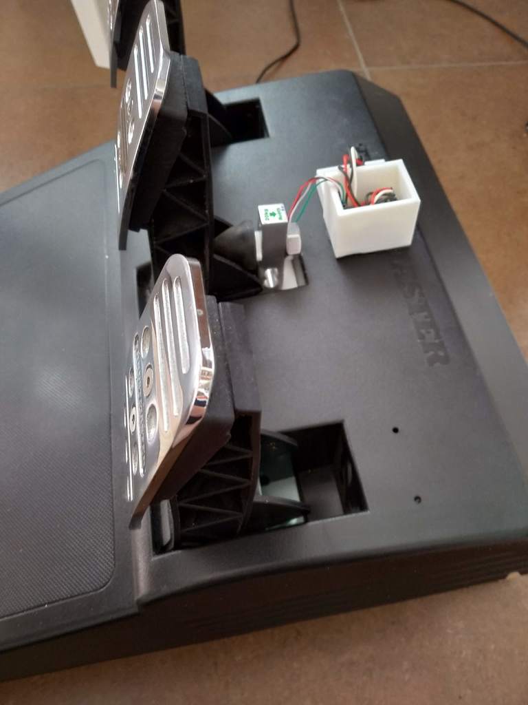
<iframe width="560" height="315" src="https://www.youtube.com/embed/7J9-i1W0CII" frameborder="0" allow="autoplay; encrypted-media" allowfullscreen></iframe> Introduction ==================== This is how you can add a loadcell to your T3PA pedals and thus improve the brake fell in your favorite racing simulation. Requirements ==================== What you need: - Thrustmaster T3PA pedals - Aruduino Pro Micro(~4$) (Arduino Micro, Due or Leonardo should also be possible) [link](https://de.aliexpress.com/item/Pro-Micro-ATmega32U4-5V-16MHz-Replace-ATmega328-For-Arduino-Pro-Mini-With-2-Row-Pin-Header/32808519179.html?spm=a2g0s.9042311.0.0.4aff4c4d47Hqr2) - Loadcell (~2$) [link](https://de.aliexpress.com/item/WAVGAT-Digital-Load-Cell-Weight-Sensor-20KG-Portable-Electronic-Kitchen-Scale-HX711-Weighing-Sensors-Ad-Module/32848782741.html?spm=a2g0s.9042311.0.0.27424c4dU5Wlor). - HX711 breadbord with adjustable framerate (~2$) [link](https://de.aliexpress.com/item/HX711-W-gesensoren-24-bit-A-D-Conversion-Adapter-W-gezelle-Verst-rkerplatine-Gewicht-Sensoren/32848866947.html?spm=a2g0s.9042311.0.0.27424c4duXF5Gx) - some cables - 2xM5x12 bolts - 1xM5 nut Instructions: ==================== 0. Remove the conical brake mod from your T3PA pedals 1. Print the brakeMod_part2.stl (loadcell holder) 2. Mount the loadcell to the printed loadcell holder using the two M5 bolts 3. Insert the M5 nut into the loadcell holder 4. Mount the loadcell holder to your T3PA pedals using the original M5 bolt from the conical brake mod 5. Attach conical rubber to loadcell _Option 1_: Cut out a piece of aluminum/stell where you can mount the conical rubber on and screw it onto the loadcell, see images. _Option 2_: Drill a 8mm hole throuh the inner M4 hole and cut a M10 threat through that hole. Screw the conical rubber directly to the loadcell. You may also want to use the circlip, which you find as a stl file. To mount the circlip, screw out the conical rubber and slide the circlip onto the conical rubber thread. 6. mount the arduino to the T3PA pedals 7. Cut the circuit path like shown in one of the images. This will increase the readout rate from the loadcell from 10Hz to 80Hz 8. Connect the loadcell to the breadboard 9. Connect the breadboard vcc --> arduino vcc 10. Connect the breadboard gnd --> Arduino gnd 11. Connect the breadboard DAT: _Option 1_: If you have an Arduino (Pro) Micro, breadboard DAT --> Arduino 2 _Option 2_: If you have an Arduino Due, breadboard DAT --> Arduino A7 11. Connect the breadboard CLK: _Option 1_: If you have an Arduino (Pro) Micro, breadboard DAT --> Arduino 3 _Option 2_: If you have an Arduino Due, breadboard DAT --> Arduino A8 12. Open the attached arduino file 13. Install the HX711_ADC library [link](https://github.com/olkal/HX711_ADC) and modfy it's "HX711_ADC.h", so that the value of "SAMPLES" is set to 4. This will decrease the low pass filter order and thus make it faster. 14. Connect the arduino via programming USB port 15. Flash the arduino with the attached file. _Option 1_: If you have an Arduino (Pro) Micro, please flash the file "brakeMod_Arduino_Pro_Micro_EEPROM.ino" _Option 2_: If you have an Arduino Due, please flash the file "brakeMod_Arduino_Due.ino" _Option 3_: If you have an Arduino Due with external EEPROM, please flash the file "brakeMod_Arduino_Due_EEPROM.ino" 16. Connect the arduino via native USB port 17. Loadcell calibration _Option 1_: If you have an Arduino (Pro) Micro, open the Arduino IDE. Connect the Arduino to the PC. Open "Serial monitor" and type "calibrate", hit send. During the next 10 seconds hit the pedal mutliple times. The arduino will read the Loadcell and automatically adjust the Loadcell readings and map it correctly. _Option 2_: If you have an Arduino Due, during the first 10 seconds after you connect the Arduino to the PC, you need to press the brake hard and fully realese it multiple times. It will read the readout limits and use them for proper scaling the readout values. During the calibration time, you will see the internal Arduino LED blinking with 1Hz. After the calibration time, it will turn of the LED. This procedure needs to be repeated everytime you connect the arduino to the PC. 18. Install the Arduino joystick Library [link](https://github.com/MHeironimus/ArduinoJoystickLibrary) 19. Open your racing simulation and adjust your controller settings the use the value from the arduino instead of the brake signal from the T3PA Edit 08.10.2018: Attached the "BrakerBumper1.stl" file, which you can use instead of the original rubber cone. It gives a much softer brake feel, similar to that in my private vehicle. Print with TPU with 4 perimeters, 15% infill, no top & bottom layer as seen in the images to achieve best possible braking feel. Note: I also attached files for a loadcell rubber contraption (holder + rubber). Tested the rubber printed it TPU, but it was not soft enough. In case somebody has softer filament, please tell me!
With this file you will be able to print Thrustmaster T3PA DIY Loadcell mod (T300, T500) < 10$ with your 3D printer. Click on the button and save the file on your computer to work, edit or customize your design. You can also find more 3D designs for printers on Thrustmaster T3PA DIY Loadcell mod (T300, T500) < 10$.