Tiny Pulse Motor
thingiverse
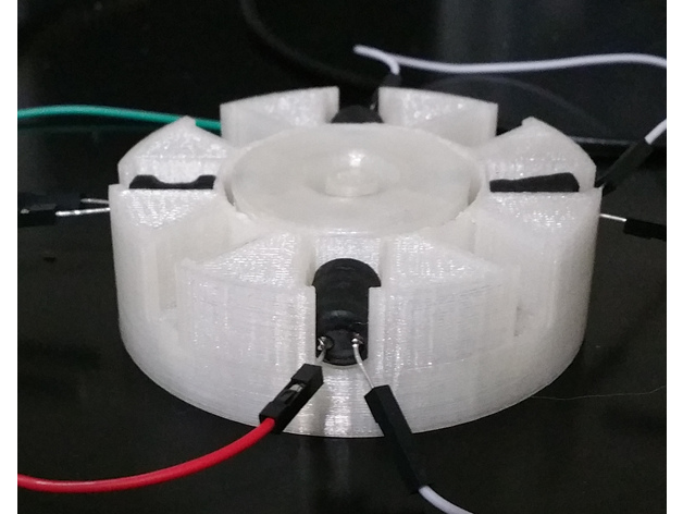
This is my latest pulse motor, a culmination of refinements from previous versions. The last pulse motor I published was rather slow and power-hungry. This one is significantly better. I've run it at 12000 RPM using an Arduino controller. I also spent some time tweaking a Bedini-style circuit which topped out at over 6700 RPM. The circuit is quite interesting too, so I thought I'd share that along with the updated motor design. I was very pleased to be able to reduce the current draw to 7mA at 12.6V while maintaining 2500+ RPM. Very impressive indeed. In all tests, I only configured it for a single pole, but the stator has slots for a second pole if desired. Feel free to build one and comment. Feedback and observations are highly appreciated. Be sure to observe safety precautions when operating at high speeds. Print Settings: Rafts: No Supports: No Resolution: 0.25 Layer 0.4 Nozzle Infill: 10% Triangle Notes: 3 Perimeters, 3 Solid Layers. Build Notes: Attach magnets to the rotor using a good quality superglue. I recommend Gorilla brand superglue with the brush applicator as it has proven reliable. Apply glue inside where the magnets sit. Insert magnets so that the same pole faces outward (i.e., all north or all south). For the Bedini-style circuit, orientation doesn't matter much but if you plan to use it with a unipolar hall sensor as the switching mechanism then plan accordingly. After placing magnets apply superglue evenly over the face of the rotor and magnets to create a protective seal that will hold the magnets in place when spinning. Let sit for several hours before using to ensure glue is entirely dry. Place 3 drive inductors in 3 opposing faces and the trigger inductor in the fourth opposing slot. The three drive coils should be wired in series so that when power is applied they repel the magnets. The rotor will require a vigorous spin to get started as it needs enough speed to create the required voltage in the trigger coil. Troubleshooting: Orientation of the inductors is significant. This is especially true for the Bedini-style circuit. Make sure to orient them correctly to avoid any issues. Where to Buy: The electronic components can be purchased from Amazon, Arrow, Digikey, Aliexpress, and/or eBay. It just depends on how much you want to pay and how long you are willing to wait. Can cost as little as 20.00 to buy the parts with tons of left overs for other projects. Part Substitution: This is experimental and unproven, but I thought I'd share my opinion on substituting the inductors with different sizes/values since it may be hard to find these exact inductors. Aside from reworking the stator to accommodate the new size, what is probably most important when determining which inductors to use is to try and match the DC resistance value of the inductors. Tinkercad Links: You can customize this and make changes easily using TinkerCad and the links below. Rotor: https://tinkercad.com/things/jYTHk48xppS Stator: https://tinkercad.com/things/bXfB11x2pdw
With this file you will be able to print Tiny Pulse Motor with your 3D printer. Click on the button and save the file on your computer to work, edit or customize your design. You can also find more 3D designs for printers on Tiny Pulse Motor.